To Modify a Route
Modifying the Path
Use the reroute option to route an existing cable or wire along another existing path.
Click here to access the downloads page. Click English to download the cabling.zip folder to your computer and then extract it. The extracted folder contains the files that you will use in the exercise. Refer the cabling_assembly.asm assembly as example to learn how to reroute wires and cables in the cabling model. Set REROUTE as the working harness. Select REROUTE from the  Saved Orientations list.
Saved Orientations list.1. Click  . The Reroute Cables tab opens.
. The Reroute Cables tab opens.2. Click the Source tab and select one of the following options from the Path type list to define the route that you want to modify:
◦ Segments—Select the segment that you want to reroute. When a segment has intermediate locations, only the selected sub-segment bounded by locations is rerouted. You can select more than one segment.
You can select a wire, conductor, cable, or bundle segment. When you select a cable or bundle, you cannot select individual conductors. |
◦ Locations—Select the start and end location points of the segment that you want to reroute. To edit a location, right-click the location box and click Remove or right-click in the graphics window and select Clear.
You can define the source route by right clicking in the graphics window and selecting the source segment or the segment start and end locations.
All segments that share a common path between the locations are automatically selected. To remove a network, cable, or wire from the list, clear the Include check box in the Cables to reroute list. |
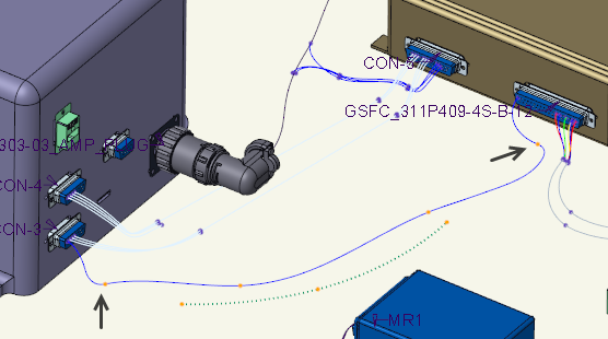
In the sample assembly, select Locations from the Path type list and select the source locations as shown in the figure.
3. On the Target tab, define the start and end locations for the new path. Alternatively, click the  collector and select a start location, and click the other collector and select an end location.
collector and select a start location, and click the other collector and select an end location.• The end collector is automatically activated on selection of the start location. If the collector is not activated, click and then select an end location.• When the target start and end locations have more than one segment path, the Use path of options are available. Select the segment path to follow. |
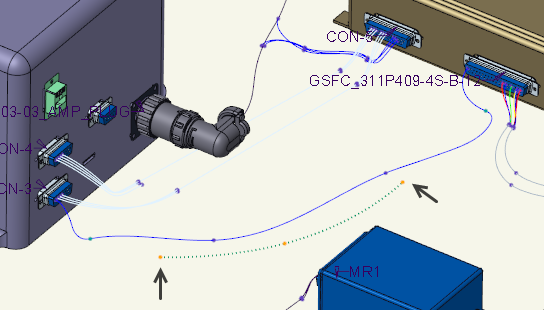
In the sample assembly, select the target locations as shown in the figure.
4. Click  . The segment is routed through the new path.
. The segment is routed through the new path.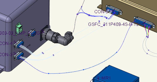
To Transfer Wire Connections Between Components
Wires with Logical Data
1. Modify and load the XML data.
2. Click  Update. The logical references update.
Update. The logical references update.3. Select the cable with modified logical data in the Model Tree or graphics window, right-click, and choose Route from the shortcut menu. The cable route updates to the new entry ports.
Wires without Logical Data
1. Select the cable in the Model Tree or graphics window, right-click, and choose Route from the shortcut menu. The Route Cables dialog box opens.
2. Select the cable conductor from the list.
3. Right-click the From or To location and choose Remove from the shortcut menu.
4. Select a new entry or end port.
5. Click OK. The cable route updates to the new port.
To Split Cables and Ribbon Cables
1. Click  Split. You are prompted to select a cable.
Split. You are prompted to select a cable.2. Select a cable that you want to split.
3. Select a location at which you want to split the cable and click OK. The harness is regenerated.
4. At the prompt, type different names for the two separate cables. The cable is split into two separate cables at the selected location.
You can split a ribbon cable at a location point that satisfies the following criteria: • The location point is a through point. • The location point is at the end of a ribbon cable trajectory or the ribbon cable has already been split at the location point. |