Detail Options
2d_region_columns_fit_text
Determines whether each column in a two-dimensional repeat region automatically resizes to fit the longest piece of text in each column, and does not overlap adjacent columns or force large gaps in the table.
Columns with no text in them use the default column width for the region (the width of the template cell).
Default and Available Settings:
• yes—Resizes each column in 2-D repeat regions to fit the longest piece of text.
• no*—Column maintains the same size.
|
|
Columns of tables that contain automatically resized two-dimensional repeat regions cannot be manually resized.
|
allow_3D_dimensions
Determines if dimensions are shown in isometric views.
Default and Available Settings:
• no*—Dimensions are not shown in isometric views.
• yes—Dimensions display in isometric views.
ang_unit_lead_zeros
Determines if leading zeros are kept when showing angular dimension in degree format. This is to support ASME Y14.5 standard.
Default and Available Settings:
• yes*—Leading zeros are kept.
• no—Leading zeros are removed.
ang_unit_trail_zeros
Determines if trailing zeros (ANSI standard) are kept when angular dimensions are shown in deg/min/sec format.
Default and Available Settings:
• yes*—Trailing zeros are kept.
• no—Trailing zeros are removed.
apply_view_scale_for_shown_syms
Controls size of a variable drawing units symbol when the symbol in model is shown in drawing.
• yes*—Symbol size updates with the drawing view scale and maintains its proportion with the 3D model.
• no—Symbol size does not update with the view scale.
arrow_style
Controls the style of the arrow head for all detail items that appear with arrows. If you retrieve a legacy model with arrow heads, the arrow style changes based on the default value.
Default and Available Settings:
• filled*—The arrow head appears filled.
• open—The arrow head appears open.
• closed—The arrow head appears closed.
associative_dimensioning
Associates draft dimensions to draft entities. The system associates only dimensions that you create while you have this set to "yes".
Default and Available Settings:
• yes*—Associates draft dimensions to draft entities.
• no—Does not associate draft dimensions to draft entities.
aux_view_note_format
Defines the default format for auxiliary view notes. The default format is VIEW%viewname-%viewname. Alternatively, type a view label in the formats View %viewname, %viewname, or Aux View %viewname.
axis_interior_clipping
Determines the ability to clip (or drag) the interior ends of an axis.
Default and Available Settings:
|
no*
|
Only allows clipping of external axes ends. 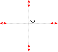 |
|
yes
|
Enables clipping of axes from both internal and external ends. 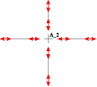 |
axis_line_offset
Sets the default distance that a linear axis extends beyond its associated feature.
Default and Available Settings:
• 0.100000*
|
|
The drawing_units Detail option determines the unit of measurement for the axis_line_offset Detail option.
|
basic_dim_to_leader_offset
no*/yes
Determines whether to add an offset between the frame of a basic dimension and the leader line.
blank_zero_tolerance
Controls the display of a plus or minus tolerance value.
Default and Available Settings:
• no*—Displays a plus or minus tolerance value if you set the tolerance value to zero.
• yes—Does not display a plus or minus tolerance value if you set the tolerance value to zero.
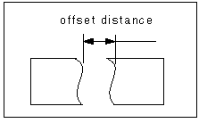
broken_view_offset
1.000000*, value
Sets the offset distance between the two halves of a broken view.
|
|
The drawing_units Detail option determines the unit of measurement for the broken_view_offset Detail option.
|
circle_axis_offset
1.100000*
Sets the default distance that a circular cross-hair axis extends beyond the circular edge.
The drawing_units Detail option determines the unit of measurement for the circle_line_offset Detail option. |
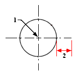
1. Circular cross-hair axis
2. The distance at which the circular cross-hair axis extends beyond the circular edge. This distance is specified by the circle_axis_offset Detail option
clip_diam_dimensions
Automatically clips the diameter dimensions at the view border. Dimension endpoints outside of the view border are clipped to the view border. No clipping occurs when both endpoints are inside view border.
Default and Available Settings:
• yes*—Automatically clips the diameter dimensions at the view border.
• no—Does not automatically clips the diameter dimensions at the view border.
The default setting is no for drawings created in earlier releases. |
clip_dim_arrow_style
double_arrow*, arrowhead, dot, filled_dot, arrow, slash, integral, box, filled_box, target, none
Controls the arrow style of clipped dimensions.
The arrow style of the clipped dimensions changes only after you click Apply in the Options dialog box. |
clip_dimensions
Controls the display of dimensions in a detailed view.
Default and Available Settings:
• yes*—Does not display dimensions completely outside of a detailed view boundary; shows dimensions that cross a detailed boundary with a double arrow.
• no—Displays all dimensions.
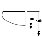 | When set to yes, dimensions that cross a detailed boundary display with a double arrow. |
create_area_unfold_segmented
Makes the display of dimensions in area unfolded cross-sectional views similar to those in total unfolded cross-sectional views.
This option only affects new views. Creo Parametric does not support detailed views of segmented area unfolded cross-sectional views or total unfolded cross-sectional views. However, it does support detailed views of non-segmented area unfolded cross-sectional views.
Default and Available Settings:
• yes*—Displays the view in segments when creating a new view—one piece at a time—corresponding to the straight segments of the cross-sectional sketch.
• no—Does not display the view in segments when creating a new view.
To draw view borders between view segments, set show_total_unfold_seam to yes. |
crossec_arrow_length
0.187500*
Sets the length of the arrowhead for cross-section cutting plane arrows.

1. The length of the arrowhead as specified by the crossec_arrow_length Detail option
The drawing_units Detail option determines the measurement unit for the crossec_arrow_length Detail option. |
crossec_arrow_style
tail_online*, head_online
Determines which end of the cross-section arrow touches the cross-section line.
tail_online—The tail of the cross-section arrow touches the cross-section line
head_online—The head of the cross-section arrow touches the cross-section line
tail_online* |  |
head_online |  |
crossec_arrow_width
0.062500*
Sets the width of the arrowhead on the cross-section cutting plane arrows.

1. The width of the arrowhead as specified by the crossec_arrow_width Detail option
The drawing_units Detail option determines the unit of measurement for the crossec_arrow_width Detail option. |
crossec_text_place
Sets the location of cross-section text.
Default and Available Settings:
after_head* |  |
before_tail |  |
above_tail |  |
above_line |  |
no_text | Does not display any cross-section text. |
crossec_type
Improves the ability to create complicated cross section views in drawings, and reduces or eliminates the number of occurrences when a cross section view cannot be created.
Default and Available Settings:
• old_style*—The system uses a cut to remove geometry to create the cross section view.
• new_style—The system uses a z-clipping plane to create the cross section view.
cutting_line
Controls the standard for the cutting line display.
Default and Available Settings:
• std_ansi*—Uses the ANSI standard for cutting lines.
• std_din—Displays the thickened portion of the cutting line in white, and displays its thin portion in gray.
• std_iso—Uses the ISO standard for cutting lines.
• std_jis—Uses the JIS standard for cutting lines.
• std_ansi_dashed—Displays the cutting line as dashed lines.
• std_jis_alternate—If set to "std_jis_alternate" and the Detail option "cutting _line_segment" is set, displays view arrows as follows:
◦ The thickened portion of the cutting line forms an angle and the system displays it in blue.
◦ Displays the connecting portions of the cutting line segment between thickened segments in yellow.
◦ Displays arrow portions in white.
• std_eskd—Uses the ESKD standard for cutting lines.
◦ Displays only the end portions of the cutting line and any corners in the internal portion of the cutting line.
◦ The cutting line is extended beyond the point where it touches the arrow. The length of the extended portion of the cutting line is determined by the value of the detail option crossec_arrow_width that defines the width of the arrow head.
• std_gb—Uses the GB standard for cutting lines.
◦ Displays only the end portions of the cutting line and any corners in the internal portion of the cutting line.
◦ The cutting line ends exactly at the point where it touches the arrow.
If you set the cutting_line_segment detail option to 0, the entire cutting line appears as a dashed line. However with ESKD and GB standards, the cutting line appears as a thin continuous line. |
cutting_line_adapt
Controls display of line fonts used to show cross-sectional arrows.
Default and Available Settings:
• no*—All line fonts do not display adaptively.
• yes—All line fonts display adaptively, beginning in the middle of a complete line segment and ending in the middle of a complete line segment.
When plotting, the section cutting line overlaps the dimension witness and leader lines. |
cutting_line_segment
Specifies the length in drawing units of the thickened portion of a non-ANSI cutting line.
Default and Available Settings:
• 0.000000*—The default length of the cutting line segment is 0. You can specify a different value, if required.
The drawing_units Detail option determines the unit of measurement for the cutting_line_segment Detail option. |
cutting_line_segment_thickness
Sets the thickness of the cutting line segment that appears at the ends and at any internal corners of the cutting line.
Default and Available Settings:
0*—The default thickness of the cutting line segment is 0.
• The cutting_line_segment_thickness detail option does not affect the thickness of cutting line with cutting_line detail option set as std_ansi or std_ansi_dashed. • Non-zero values of cutting_line_segment_thickness and cutting_line_segment detail options affect the display of a cutting line with std_din, std_iso, std_jis, std_jis_alternate, std_eskd, or std_gb standard. • If the value of cutting_line_segment detail option is set to zero, the cutting_line_segment_thickness detail option has no effect on the display of the cutting line. |
dash_supp_dims_in_region
Controls display of dimension values in Pro/REPORT table repeat regions.
Default and Available Settings:
• yes*—Suppresses the dimension and displays a dash instead.
• no—Displays the values in Pro/REPORT table repeat regions.
datum_point_shape
Controls display of dimension values in Pro/REPORT table repeat regions.
cross*, dot, circle, triangle, square
Determines the display of datum points.
datum_point_size
Controls size of model datum points and sketched two-dimensional points.
Default and Available Settings:
• 0.3125*—Reverts to the setting established in the drawing_units Detail option; which has a default setting of inches. You can type a value for the datum point size.
The drawing_units Detail option determines the unit of measurement for the datum_point_size Detail option. |
datum_target_outside_text
Allows you to set the default position of the datum target area size text relative to the elbow in a case when the size text is displayed outside of the datum target frame This option provides you with two values:
• near_elbow — When the datum_target_outside_text is set to near_elbow, the fixed size elbow of the standard length is used. The text is located near the elbow. The text is vertically centered with the elbow. This value is set by default.
• above_elbow — When the datum_target_outside_text is set to above_elbow, the text is located above the elbow. The length of the elbow depends on the length of the text string.
Switching the value of the datum_target_outside_text option affects all datum target symbols available in the current model or drawing. When a value of the datum_target_outside_text option is changed. All the datum target symbols are updated according to the chosen option where the size text is displayed outside the symbol frame
decimal_marker
comma_for_metric_dual*, period, comma
Specifies the character to be used as the decimal point in secondary dimensions.
def_bom_balloons_attachment
Sets the default attachment method for BOM balloons.
Default and Available Settings:
• edge*—BOM balloons point to component edges.
• surface—BOM balloons point to component surfaces.
For records of components that represent bulk items and included item components, the default attachment method is set.
def_bom_balloons_edge_att_sym
Controls the default leader head when BOM balloons are attached to edges.
Default and Available Settings:
• arrowhead*
• dot
• filled_dot
• no_arrow
• slash
• integral
• box
• filled_box
• target
• half arrow
• triangle
def_bom_balloons_snap_lines
Determines whether snap lines are created around the view when showing BOM balloons.
Default and Available Settings:
• no*
• yes
def_bom_balloons_stagger
Determines whether BOM balloons are displayed in a staggered manner by default.
Default and Available Settings:
• no*
• yes
def_bom_balloons_stagger_value
Controls the distance between consecutive offset lines when BOM balloons are displayed in a staggered manner.
Default and Available Settings:
• 0.600000*
def_bom_balloons_surf_att_sym
Controls the default leader head when BOM balloons are attached to surfaces.
Default and Available Settings:
• integral*
• arrowhead
• dot
• filled_dot
• no_arrow
• slash
• box
• filled_box
• target
• half arrow
• triangle
def_bom_balloons_view_offset
Controls the default offset distance from the view boundaries on which to show BOM balloons.
Default and Available Settings:
• 0.800000*
def_xhatch_break_around_text
Determines if cross section/hatch lines break around text.
Default and Available Settings:
• no*—Cross section/hatch lines do not break around text.
• yes—Cross section/hatch lines break around text.
def_xhatch_break_margin_size
Sets the default offset distance (in drawing units) between the cross section lines and text.
Default and Available Settings:
• 0.150000*
def_view_text_height
Sets the text height in view names used in view notes, and in arrows in cross-sectional and projection detail views.
Default and Available Settings:
0.000000*
The drawing_units Detail option determines the unit of measurement for the def_view_text_height Detail option. |
def_view_text_thickness
Sets default thickness for new text in view names used in view notes and in arrows in newly created cross-sectional and projection detail views.
Default and Available Settings:
0.000000*
The drawing_units Detail option determines the unit of measurement for the def_view_text_thickness Detail option. |
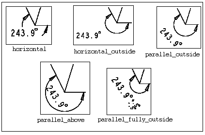
default_angdim_text_orientation
Controls the default text orientation for angular dimensions, except when in center leader configuration.
Default and Available Settings:
• horizontal*—Displays text of angular dimensions horizontally at all times, centered between the leaders.
• parallel_outside—Displays text parallel to the leader lines, regardless of their orientation.
• horizontal_outside—Displays text horizontally outside the dimension.
• parallel_above—Displays text parallel to the dimension arc, but above it.
• parallel_fully_outside—Displays text of angular dimensions (with a plus/minus tolerance) parallel to the leader lines.
default_annotation_font
Specifies the default text font for the annotations.
Include the file extension (such as .ndx, .ttf, or .otf), if the font directory contains multiple files with the same name.
default_ansi_ord_dim_aligned
yes*, no
Specifies whether ordinate dimensions are aligned with the baseline dimension when you create dimensions with the Detail option ord_dim_standard set to std_ansi.
default_bom_balloon_type
Defines the default BOM balloon type when you create BOM balloons.
Default and Available Settings:
• simple_circle*
• quantity_split_circle
• <custom balloon symbol name>
default_bend_table_font
Specifies the default font for the bend tables. Some fonts may not be best represented in the table. Specifically, variable-width fonts lack vertical alignment between the columns of the table. For best results, use a fixed-width font.
• font.ndx*—Uses the font.ndx font.
• default_font—Uses the font specified in the default_annotation_font Detail option.
• <any other font name>—Uses the font specified by the user.
Include the file extension (such as .ndx, .ttf, or .otf), if the font directory contains multiple files with the same name. |
default_chamf_dim_configuration
Sets the default configuration for the chamfer dimension.
Default and Available Settings:
• leader*—Creates the chamfer as per the chamfer leader style.
• linear—Creates the chamfer with STD_DIN display style.
default_chamf_text_orientation
Controls the text orientation for 45-degree chamfer dimensions in drawings.
Default and Available Settings:
• next_to_and_centered_about_elbow *—Places the dimension text in the horizontal position. The dimension text is vertically centered about the elbow line (ASME standard).
• next_to_and_above_elbow—Places the dimension text in the horizontal position. The dimension text is above the elbow line (ISO standard).
• above_extended_elbow—Places the dimension text in the horizontal position. The elbow is below the dimension text and extends to the width of the dimension text (ISO standard).
• parallel_to_and_above_leader—Places the dimension text parallel to and above the leader line (JIS standard).
• parallel_to_and_below_leader—Places the dimension text parallel to and below the leader line (JIS standard).
default_chamfer_text
Controls the display of dimension text of 45-degree chamfer dimensions in drawings.
Default and Available Settings:
• 45xd* —Displays chamfer dimension label as 45xd (ASME/ANSI Standards)
• dx45 —Displays chamfer dimension label as dx45 degrees (ISO/DIN Standards)
• cd —Displays chamfer dimension as cd (JIS Standard)
• d —Displays chamfer dimension as set in the Display group of the Dimension ribbon tab.
This Detail option does not affect the three-dimensional model. |
default_dual_dim_position
Sets the default position for dual dimension values. Only applicable to newly created dimensions. The display for this option is valid when the dual_dimensioning Detail option is set to primary[secondary] or secondary[primary].
Default and Available Settings:
• below* —Sets the secondary dimension below the primary dimension.
• right—Sets the secondary dimension to the right of the primary dimension.
default_cldim_text_orientation
Sets the default text orientation for dimensions set to center leader configuration.
Default and Available Settings:
• next_to_and_centered_about_elbow*–Places the dimension text in the horizontal position. The dimension text is vertically centered about the elbow line (ASME standard).
• next_to_and_above_elbow—Places the dimension text in the horizontal position. The dimension text is above the elbow line (ISO standard).
• above_extended_elbow—Places the dimension text in the horizontal position. The elbow is below the dimension text and extends to the width of the dimension text (ISO standard).
• parallel_to_and_above_leader—Places the dimension text parallel to and above the leader line (JIS standard).
• parallel_to_and_below_leader—Places the dimension text parallel to and below the leader line (JIS standard).
default_clean_dim_increment
Specifies the default value for the Increment field in the Clean Dimensions dialog box. The value specified for this option is applied to the Increment field only the first time you access the Clean Dimensions dialog box in a Creo Parametric session. Thereafter, any changes that you make to the Increment field value are retained as long as the drawing is in session.
Default and Available Settings:
0.375 inch (range (0-22))
default_clean_dim_offset
Specifies the default value for the Offset field in the Clean Dimensions dialog box. The value specified for this option is applied to the Offset field only the first time you access the Clean Dimensions dialog box in a Creo Parametric session. Thereafter, any changes that you make to the Offset field value are retained as long as the drawing is in session.
Default and Available Settings:
0.5 inch (range (0-22))
default_detail_view_name_style
Controls the manner in which default name is assigned to a new detailed view.
• letter*—Assigns the next available Latin alphabet letter to the new detailed view.
• roman—Assigns the next available uppercase Roman numeral to the new detailed view.
default_diadim_text_orientation
Sets the default text orientation for diameter dimensions.
Default and Available Settings:
• next_to_and_centered_about_elbow*–Places the dimension text in the horizontal position. The dimension text is vertically centered about the elbow line (ASME standard).
• next_to_and_above_elbow—Places the dimension text in the horizontal position. The dimension text is above the elbow line (ISO standard).
• above_extended_elbow—Places the dimension text in the horizontal position. The elbow is below the dimension text and extends to the width of the dimension text (ISO standard).
• parallel_to_and_above_leader—Places the dimension text parallel to and above the leader line (JIS standard).
• parallel_to_and_below_leader—Places the dimension text parallel to and below the leader line (JIS standard).
default_dim_elbows
Controls display of dimension elbows.
Default and Available Settings:
• yes*—Dimensions display with elbows.
• no—Dimensions do not display with elbows.
default_hatch_type
Sets the default crosshatch pattern file type to be used in models and drawings:
• xch*—Sets .xch as the default file type.
• pat—Sets .pat as the default file type.
default_font
Specifies the default text font filename including the file extension.
Default and Available Settings:
• font.ndx*—This is the default font filename. You can specify a different font file, if required.
The font (font and filled) are located in the setup file. |
default_leader_arrow_style
Sets the default arrow style for new leaders attached to geometry.
Default and Available Settings:
• automatic*—Sets the arrow style based on the reference type as follows:
Reference | Arrow Style |
|---|---|
Surface and Quilt | filled dot |
Entity/Edge, Silhouette Edge, Curve, Sketch, and Free Point | arrow head |
Datum Point, Datum Axis, Datum Csys, and Cosmetic Sketch | no arrow |
• dot
• filled dot
• slash
• integral
• box
• filled box
• no arrow
• arrow head
• double arrow
• half arrow
• target
• triangle
Leader attachments to non-geometric objects are not affected by this option. |
default_lindim_text_orientation
Sets the default text orientation for linear dimensions, except when in center leader configuration.
Default and Available Settings:
• horizontal*–Places the dimension text horizontal to the leader line.
• parallel_to_and_above_leader—Places the dimension text parallel to and above the leader line (JIS standard).
• parallel_to_and_below_leader—Places the dimension text parallel to and below the leader line (JIS standard).
default_note_leader_type
Controls the standard-compliant representation of leader notes.
Default and Available Settings:
• std_asme*—Note annotations appear centered on the leader’s elbow.
• std_iso—Note annotations appear above an extended elbow.
default_orddim_text_orientation
Sets the default text orientation for ordinate dimensions (parallel to witness lines).
Default and Available Settings:
• parallel_to_and_centered_about_leader*—Places the dimension text parallel to the leader line.
• parallel_to_and_above_leader— Places the dimension text parallel to and above the leader line (JIS standard).
• parallel_to_and_below_leader— Places the dimension text parallel to and below the leader line (JIS standard).
• horizontal—Places the dimension text horizontally, parallel to the bottom of the drawing sheet.
default_pipe_bend_note
Controls display of pipe bend notes in drawings.
If set as text within quotation marks, uses that value when creating bend notes. Text may include parameters such as "&bend_name:att_pipe_bend" and "&bend_tol: att_pipe_bend".
If set as a directory path, references a previously created note saved as a file.
Default and Available Settings:
• no*—Pipe bend notes do not display in drawings.
• yes—Pipe bend notes display in drawings.
default_raddim_text_orientation
Sets the default text orientation for radius dimensions.
Default and Available Settings:
• next_to_and_centered_about_elbow*–Places the dimension text in the horizontal position. The dimension text is vertically centered about the elbow line (ASME standard).
• next_to_and_above_elbow—Places the dimension text in the horizontal position. The dimension text is above the elbow line (ISO standard).
• above_extended_elbow—Places the dimension text in the horizontal position. The elbow is below the dimension text and extends to the width of the dimension text (ISO standard).
• parallel_to_and_above_leader—Places the dimension text parallel to and above the leader line (JIS standard).
• parallel_to_and_below_leader—Places the dimension text parallel to and below the leader line (JIS standard).
default_show_2d_section_xhatch
Controls the display of crosshatches for newly created 2D cross-sections for assemblies and parts.
Default and Available Settings:
• assembly_and_part*—Displays crosshatches for both assembly and part 2D cross-sections.
• assembly_only—Displays crosshatches only for assembly 2D cross-sections.
• part_only—Displays crosshatches only for part 2D cross-sections.
• no—Does not display crosshatches for assembly and part 2D cross-sections.
This Detail does not affect the display of existing 2D cross-sections. |
default_show_3d_section_xhatch
Controls the display of crosshatches for 3D cross-sections.
Default and Available Settings:
• yes*—Crosshatches are displayed for selected 3D cross-sections.
• no—Crosshatches are not displayed for selected 3D cross-sections.
default_table_column_width
Specifies the default column width in number of characters a table will have when you create a new table.
Default and Available Settings:
• 10*
default_table_columns
Specifies the default number of columns a table will have when you create a new table.
Default and Available Settings:
• 4*
The default_table_columns Detail option is read only once per drawing in a session. The first time you open the Insert Table dialog box, the Number of Columns box is populated with the value of this Detail option. Subsequent appearances of the Insert Table dialog in the same drawing, in the same session, uses the last used value of the Number of Columns text box on the Insert Table dialog box. |
default_table_row_height
Specifies the default row height in number of characters a table will have when you create a new table.
Default and Available Settings:
• 1*
default_table_rows
Specifies the default number of rows a table will have when you create a new table.
Default and Available Settings:
• 2*
The default_table_rows Detail option is read only once per drawing in a session. The first time you open the Insert Table dialog box, the Number of rows box is populated with the value of this Detail option. Subsequent appearances of the Insert Table dialog in the same drawing, in the same session, uses the last used value of the Number of rows text box on the Insert Table dialog box. |
default_tolerance_display_style
Controls the spacing and vertical justification of tolerance values relative to the nominal dimension according to ASME or ISO drawing standards.
For dimensions set to limits tolerance, this Detail option additionally controls the appearance of limits as in-line (next to each other separated by a dash) or stacked (one on top of the other). That is, when the value is set to std_asme, limits will appear in-line, and when the value is set to std_iso, limits will appear stacked.
This Detail option controls the display style of dimensions when their tolerance mode is set to anything other than nominal. |
Default and Available Settings:
• std_asme*–Applies American Society of Mechanical Engineers (ASME). Limits appear in-line.
For the desired effect, you may need to use an ASME-compliant dimension text orientation. |
• std_iso—Applies International Organization for Standardization (ISO). Limits appear stacked.
default_tolerance_mode
Sets the default tolerance mode for newly created dimensions.
Default and Available Settings:
• nominal*–Displays dimensions without tolerances.
• basic—Displays dimension in basic mode. The dimension value (nominal or overridden), without its tolerances, appears surrounded by a rectangle.
• limits—Displays dimensions as upper and lower limits.
• plusminus—Displays dimensions as a nominal with plus-minus tolerances (the positive and negative values are independent).
• plusminussym—Displays dimensions as a nominal with a single value for both the positive and negative tolerances.
• plusminussym_super—Same as plusminussym. However, displays the plus-minus tolerance value at the half-way point of the dimension text and extending upwards.
default_view_label_placement
• Section
• Scaled
• Projection
• Detailed
This option is not applicable for the following types of drawing views as they do not support the automatic creation of view labels:
• General
• Auxiliary
• Revolved
• Partial
• Broken
Default and Available Settings:
bottom_left* | The view label is placed at the bottom left of the view and the label text is right-aligned. 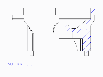 |
bottom_center | The view label is placed at the bottom center of the view and the label text is center-aligned. 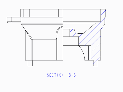 |
bottom_right | The view label is placed at the bottom right of the view and the label text is left-aligned. 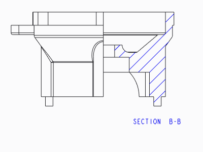 |
top_left | The view label is placed at the top left of the view and the label text is right-aligned. 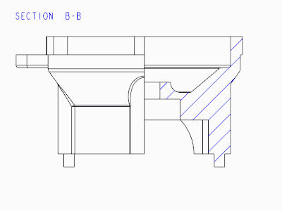 |
top_center | The view label is placed at the top center of the view and the label text is center-aligned. 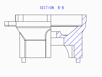 |
top_right | The view label is placed at the top right of the view and the label text is left-aligned. 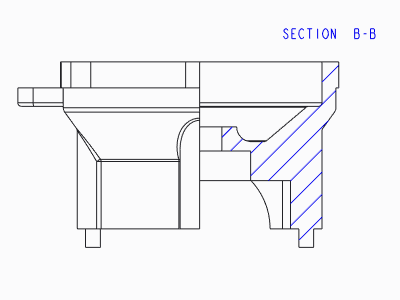 |
To display the view labels for projection views, set the make_proj_view_notes configuration option to yes.You can then use the default_view_label_placement Detail option to specify the location of the labels for these views. |
default_view_note_orientation
Controls the placement of the new detail view notes.
Default and Available Settings:
• next_to_and_centered_about_elbow*— The detail view note text is placed next to and centered about the leader elbow.
• above_extended_elbow—Creates detail view placement per the Chinese GB and Russian ESKD standards. For the GB standard, the view name is placed in the form, <view name> (<view scale>). For the ESKD standard, the view name is displayed with a horizontal line separating the view name and the view scale.
You can use the above_extended_elbow value with all values of the view_note drawing option. |
In case of the GB standard, the horizontal justification of the text within the view note depends on the value of the default_view_label_placement drawing option. |
default_z_radius_center_symbol
Determines the display of the artificial center for the z-type radius dimension.
Default and Available Settings:
• cross—Displays the artificial center as a cross.
• filled_dot—Displays the artificial center as a filled dot.
• none—Does not displays the artificial center.
detail_circle_line_style
Sets the line font for circles indicating a detailed view in a drawing.
You can select any of the above line styles, or you can set any available system-defined or user-defined line font.
Default and Available Settings:
solidfont*, dotfont, ctrlfont, phantomfont, dashfont, ctrlfont_s_l, ctrlfont_l_l, ctrlfont_s_s, dashfont_s_s, phantomfont_s_s, cntrl_font_m_l, intmit_lww_hidden, pdfhidden_linestyle
detail_circle_note_text
Determines the text displayed in non-ASME-94 detail view reference notes.
Default and Available Settings:
• DEFAULT*—Determines the default contents of the reference note for a detailed view. For example if the value is "See View" the note text reads "See View <viewname>".
• None—Enter this value manually to display the view name with no additional text.
detail_view_boundary_type
Determines default boundary type on the parent view of a detailed view.
Default and Available Settings:
• Circle*—Draws a circle in the parent view for the detailed view.
• Ellipse—Draws an ellipse in the parent view for the detailed view to closely match the spline, and prompts you to select an attachment point on the ellipse for the view note.
• H/V Ellipse—Draws an ellipse with a horizontal or vertical major axis and prompts you to select an attachment point on the ellipse for the view note.
• Spline—Displays the actual spline boundary on the parent view for the detailed view, and prompts you to select an attachment point on the spline for the view note.
• ASME 94 Circ —Displays an ASME standard compliant circle in the parent view as an arc with arrows and the detailed view name.
detail_view_circle
Sets display of a circle drawn about the portion of a model that is detailed by a detailed view.
Default and Available Settings:
• on*—Displays a circle about the detailed portion of a model.
• off—Does not display a circle about the detailed portion of a model.
detail_view_scale_factor
Determines default scale factor between a detail view and its parent view.
Default and Available Settings:
• 2.000000*—Detail view scale is twice that of its parent view.
dim_dot_box_style
Controls the arrow style display of dots and boxes only for the leaders of linear dimensions.
• default*—Uses the style defined by the arrow_style drawing option. The default arrow style of BOM balloon is defined by the def_bom_balloons_edge_att_sym and def_bom_balloons_surf_att_sym Detail options.
• filled—Fills dots and boxes for arrows of linear dimensions. Use "filled" to have new drawings appear with dots and boxes filled for dimension arrows.
• hollow—Dots and boxes for arrows of linear dimensions are not filled.
dim_fraction_format
Controls the display of fractional dimensions within drawings.
This Detail option supersedes the configuration file option of the same name (dim_fraction_format) unless the Detail option is set to default.
Default and Available Settings:
• default*—Displays fractional dimensions in drawings according to the setting of the configuration file option dim_fraction_format.
• std—Displays fractional dimensions in drawings in the standard Creo Parametric format.
• aisc—Displays fractional dimensions in drawings in the AISC format. The AISC setting also displays architectural units according to AISC format for feet-inches dimensions.
When you retrieve drawings created prior to Pro/ENGINEER Release 2000i, the dim_fraction_format and use_major_units Detail options combine to control the display of dimensions. |
dim_leader_length
Sets the length of the dimension leader lines when the leader arrows are outside the witness lines.
Default and Available Settings:
0.500000*

1. The length of the dimension leader line of the leader arrow that is outside the witness lines. The length is equal to the value specified by the dim_leader length Detail option.
The drawing_units Detail option determines the unit of measurement for the dim_leader_length Detail option. |
dim_text_break_witness_line
Controls the appearance of the dimension line or witness line that overlaps dimension text.
Default and Available Settings:
• yes*—The dimension or the witness line will appear broken where it overlaps dimension text.
• no—The dimension or the witness line will not appear broken where it overlaps dimension text.
dim_text_gap
Controls the distance between dimension text and dimension leader line and represents the ratio between gap size and text height.
Default and Available Settings:
0.500000*

For diameter dimensions, it controls the extension of an elbow beyond the text when its text orientation is “Above extended elbow”.

The drawing_units Detail option determines the unit of measurement for the dim_text_gap Detail option. |
dim_tol_lead_trail_zeros
Controls the appearance of leading and trailing zeroes of the dimension tolerance values that appear in any tolerance mode other than the limits and nominal format. This does not affect the appearance of angular dimension tolerance values.
Default and Available Settings:
• same_as_lead_trail_zeros*—The appearance of leading and trailing zeroes of the dimension tolerance values is same as that of dimension values set by the Detail option lead_trail_zeros.
• by_model_units—The leading and trailing zeroes of the dimension tolerance values appear according to the units of the model. If the model has English units, the leading zero does not appear and trailing zeroes are added according to the number of decimal places you have set for the dimension value. If the model has Metric units, the leading zero appears and trailing zeroes do not appear.
• trail_only—Regardless of the units of the model, trailing zeroes appear, but the leading zero does not appear.
• lead_only—Regardless of the units of the model, only the leading zero appears, while the trailing zeroes do not appear.
• both—Regardless of the units of the model, both the leading zero and trailing zeroes appear.
• by_model_units [by_secondary_units]—Primary display of the dimension tolerance values is based upon model units and secondary display is based upon the secondary units.
• by_model_units [trail_only(english)]—Primary display of the dimension tolerance values is based upon model units. Secondary units do not display a leading zero and trailing zeros are displayed as specified while inserting the dimension tolerance.
• by_model_units [lead_only(metric)]—Primary display of dimension tolerance values is based upon model units. Secondary units display a single, leading zero and trailing zeros are not displayed.
• by_model_units [both]—Primary display of dimension tolerance values is based upon model units. Secondary units display a single, leading zero and trailing zeros are displayed as specified while inserting the dimension tolerance.
• trail_only [lead_only]—Primary units do not display a leading zero and trailing zeros are displayed as entered. Secondary units display a single, leading zero and trailing zeros are not displayed.
• trail_only(english) [lead_only(metric)]—Primary units do not display a leading zero and trailing zeros are displayed as entered. Secondary units display a single, leading zero and trailing zeros are not displayed.
• trail_only(english) [trail_only(english)]—Both primary units and secondary units do not display a leading zero. Both display trailing zeros as specified while inserting the dimension tolerance.
• trail_only(english) [both]—Primary units do not display a leading zero and trailing zeros are displayed as entered. Secondary units display a single, leading zero and trailing zeros are displayed as specified while inserting the dimension tolerance.
• lead_only(metric) [trail_only(english)]—Primary units display a single, leading zero and trailing zeros are not displayed. Secondary units do not display a leading zero and trailing zeros are displayed as specified while inserting the dimension tolerance.
• lead_only(metric) [lead_only(metric)]—Both primary and secondary units display a single, leading zero and trailing zeros are not displayed.
• lead_only(metric) [both]—Primary units display a single, leading zero and trailing zeros are not displayed. Secondary units display a single, leading zero and trailing zeros are displayed as specified while inserting the dimension tolerance.
• both [both]—Both primary and secondary unit display a single, leading zero and trailing zeros are displayed as specified while inserting the dimension tolerance.
• both [trail_only(english)]—Primary units display a single, leading zero and trailing zeros are displayed as entered by you. Secondary units do not display a leading zero and trailing zeros are displayed as specified while inserting the dimension tolerance.
• both [lead_only(metric)]—Primary units display a single, leading zero and trailing zeros are displayed as entered by you. Secondary units display a single, leading zero and trailing zeros are not displayed.
The display for the above settings is valid when the dual_dimensioning Detail option is set to primary[secondary] or secondary[primary]. |
dim_tol_trail_zero_max_places
Sets the maximum number of decimal places for dimension tolerances when trailing zeros are used to attain the maximum number of decimal places defined by the default_dec_places configuration option.
Default and Available Settings:
same_as_dim_tol
• This Detail option does not affect angular dimensions displayed in the degree/minute/second format. • This Detail option does not affect the decimal places if the value specified for the lead_trail_zeros Detail option prevents trailing zeros from being displayed. |
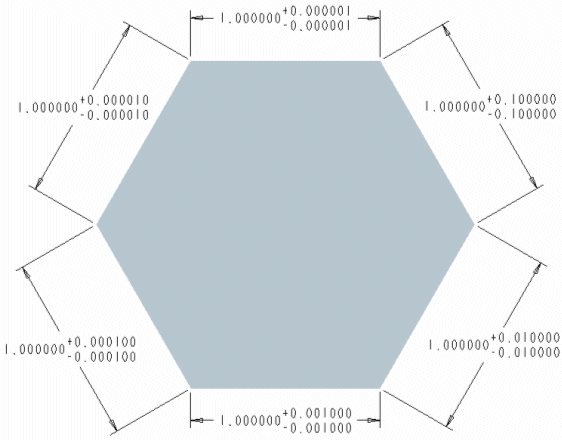
Consider the following example:
1. Specify the value 6 for the default_dec_places configuration option.
2. Retain the default value for dim_tol_trail_zero_max_places.
3. Specify the value both for lead_trail_zeros.
4. Create several dimensions with plus-minus tolerances.
Dimension tolerances are displayed as shown in the following figure:
Change the value of dim_tol_trail_zero_max_places to 3 to display the dimension tolerances as follows:
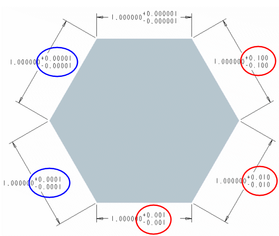
In the previous figure, tolerances with significant digits beyond 3 decimal places are displayed to the last significant digit. Subsequent trailing zeros are suppressed. Such values have been enclosed in blue circles. All trailing zeros are suppressed for tolerance values that have trailing zeros extending beyond 3 decimal places. Such values have been enclosed in red circles.
dim_trail_zero_max_places
Sets the maximum number of decimal places for dimensions and dimension tolerances when trailing zeros are used to attain the maximum number of decimal places defined by the default_dec_places configuration option. Specify a value that is less than the specified number of decimal places for dimensions to control the number of trailing zeros.
Default and Available Settings:
same_as_dim
• This Detail option does not affect decimal places if the value specified for the lead_trail_zeros Detail option prevents trailing zeros from being displayed. • This Detail option affects the display of all dimensions in a drawing. You cannot individually control the number of decimal places for dimensions with trailing zeros. • This Detail option does not affect angular dimensions displayed in the degree, minute, and second format. |
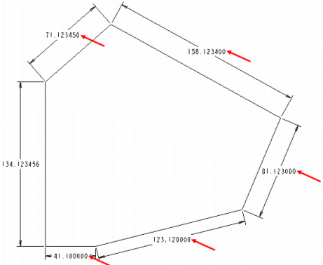
Consider the following example:
1. Specify the value 2 for the default_dec_places configuration option.
2. Specify the value same_as_dim for dim_trail_zero_max_places.
3. Specify the value both for lead_trail_zeros.
4. Click > and type the value 6. Trailing zeros are added for dimensions whose values do not extend upto 6 decimal places. Such dimensions are identified by an arrow as shown in the following figure:
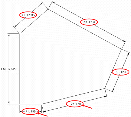
In this example, if you change the value of dim_trail_zero_max_places to 3, trailing zeros are added for all dimensions with values less than 3 decimal places. Such dimensions are identified by an arrow as shown in the following figure:
display_tol_by_1000
Displays the tolerance values for non-angular dimensions in multiples of 1000.
Default and Available Settings:
• no*—Tolerance values do not appear in multiples of 1000.
• yes—Tolerance values appear in multiples of 1000.
draft_scale
Controls the scale of draft dimensions relative to the actual length of draft entity in drawing.
Default and Available Settings:
1.000000*
The drawing_units Detail option determines the unit of measurement for the draft_scale Detail option. |
draw_arrow_length
Sets the length of leader line arrowheads.
Default and Available Settings:
0.187500*

1. The length of the leader line arrowhead as specified by the draw_arrow_length Detail option
The drawing_units Detail option determines the unit of measurement for the draw_arrow_length Detail option. |
draw_arrow_width
Sets the width of the leader line arrowheads.
Default and Available Settings:
0.062500*

1. The width of the leader line arrowhead as specified by the draw_arrow_width Detail option
• The drawing_units Detail option determines the unit of measurement for the draw_arrow_width Detail option. • The value specified by the draw_arrow_width Detail option determines the values of the draw_attach_sym_height, draw_attach_sym_width and draw_dot_diameter Detail options. |
draw_attach_sym_height
Sets height of leader line slashes, integral signs, and boxes.
Default and Available Settings:
• default*—Uses value set for draw_arrow_width
• value—Type a value for the height of leader line slashes, integral signs, and boxes.
The measurement is controlled by the drawing_units setup file option. |
draw_attach_sym_width
Sets width of leader line slashes, integral signs, and boxes.
Default and Available Settings:
• default*—Uses value set for draw_arrow_width
• value—Type a value for the width of leader line slashes, integral signs, and boxes.
The measurement is controlled by the drawing_units setup file option. |
draw_cosms_in_area_xsec
Controls display of cosmetic sketches and datum curve features that lie in the cutting plane in planar area cross-sectional views.
Default and Available Settings:
• no*—Does not show all cosmetic sketches and datum curve features that lie in the cutting plane.
• yes—Shows all cosmetic sketches and datum curve features that lie in the cutting plane.
draw_dot_diameter
Sets diameter of leader line dots.
Default and Available Settings:
• default*—Uses the value set in the draw_arrow_width Detail option.
• value—Type a value for the diameter of leader line dots.
The measurement is controlled by the drawing_units setup file option. |
draw_layer_overrides_model
Controls whether to change the display of model layers in Drawing mode only when the model layer name is the same as the drawing layer name.
• no*—Ignores model layers when the display status of layers is set in the drawing.
• yes—Changes the display of model layers in the drawing.
draw_layers_new_model_show_all
Sets the display of all model layers when a model is introduced for the first time to the drawing.
• yes*—All the model layers are displayed.
• no—All the model layers are hidden.
To set the display state of layers when switching layer tree display from drawing to view, if no explicit display state is set in the context of the view, use the configuration option def_shown_layers_in_view. |
drawing_text_color
Controls the text color in drawings.
Default and Available Settings:
• letter_color*—All the drawing texts appear with the letter color.
• edge_highlight_color—All the drawing texts appear with edge highlight color.
drawing_units
Specifies the unit for all drawing parameters.
Default and Available Settings:
inch, foot, mm, cm, m
dual_digits_diff
Controls the number of digits to the right of the decimal of the secondary dimension as compared to the primary dimension.
Default and Available Settings:
-1*
For example, if you specify -1 as the value for secondary dimensions when primary units are in inches and secondary units are in millimeters, the result is as follows:
10.235 [259.96]
dual_dimension_brackets
Controls display of brackets with dimension units.
Default and Available Settings:
• yes*—Displays dimension units that occur second in brackets;
• no—Does not display brackets.
This Detail option only works when you also set the dual_dimensioning Detail option. |
dual_dimensioning
Controls the formatting of dimension display; whether or not dual dimensions are used and also how they display.
Default and Available Settings:
• no*—Displays a single value for dimensions.
• primary[secondary]—Displays dimensions with primary units (established by the model) and secondary units.
• secondary[primary]—Displays dimensions with secondary units (established by the model) and primary units.
• secondary—Only displays the secondary dimensions of the drawing, as if they were primary.
The following Detail options can be used in conjunction with this option to modify the display of dual dimensions: • dual_secondary_units specifies the secondary set of units used by the drawing. • dual_digits_diff specifies the number of decimal places that secondary units contain compared with the primary units used. • decimal_marker specifies the character to use to mark the decimal point in secondary dimensions. • dual_dimension_brackets specifies whether one of the units of dimensions appears within brackets. |
dual_metric_dim_show_fractions
Determines whether the metric portion of dual dimension will display fractions when the primary/model units are fractions.
Default and Available Settings:
• no*—Dual dimensions do not display as fractions when the primary/model units are fractions..
• yes—Dual dimensions display as fractions when the primary/model units are fractions.
dual_secondary_units
Specifies the unit for the display of secondary dimensions in dual dimension schemes.
Default and Available Settings:
mm*, inch, foot, cm, m
exclude_affixes_from_basic_box
Controls the default sate of the Exclude Prefix/Suffix from Basic box option under the Dimension Text group on Dimension ribbon tab for the dimensions with tolerance mode set to basic.
• no*—Disables the Exclude prefix/suffix from Basic box option, to include the prefix and suffix values within the basic box of the dimension.
• yes—Enables the Exclude prefix/suffix from Basic box option, to exclude the prefix and suffix values within the basic box of the dimension.
extension_line_offset
Specifies the offset between the geometry reference and the extension line of the annotation leader arrow.
The default is 0.0625. You can specify a different value, if required.
gtol_datums
Sets the drafting standard for displaying reference datums within drawings. This affects the display of axes, datum planes, and reference part datums.
Value | Example |
|---|---|
std_ansi* |  |
std_ansi_mm |  |
std_iso |  |
std_jis |  |
std_din |  |
std_iso_jis |  |
std_ansi_dashed |  |
std_asme |  |
std_iso_1101_2017 |  |
std_asme_y14.5_2018 |  |
This Detail option also controls the leader attachment display of stacked GTOLs in drawings.
Value | Example |
|---|---|
std_iso_1101_2017 |  |
std_asme_y14.5_2018 |  |
By default, the value is set to std_asme_y14.5_2018 when you display stacked GTOLs in drawings. |
gtol_dim_placement
Determines the location of a feature control frame when a geometric tolerance is attached to a dimension symbol that contains additional text.
Default and Available Settings:
on_bottom* | Places the geometric tolerance at the bottom of the dimension symbol, beneath any additional lines of text.  |
under_value | Places the geometric tolerance immediately below the dimension value and before any additional lines of text.  |
gtol_indicator_attached
yes*, no
Specifies whether to attach the plane and feature indicators to the GTOL frame, or to leave a gap.
• yes*—Attaches the GTOL frame to the plane and feature indicators.
• no—Shows a gap between the GTOL frame, and the plane and feature indicators.
gtol_lead_trail_zeros
Controls the display of leading and trailing zeros in gtols.
Default and Available Settings:
The display for the same_as_lead_trail_zeros, by_model_units, trail_only(english), lead_only(metric), and both settings is valid when the dual_dimensioning Detail option is set to no.
• same_as_lead_trail_zeros*—The display of a single, leading zero and trailing zeros in gtol tolerance values is determined by the current value of the lead_trail_zeros Detail option.
• by_model_units—The display of the leading zero and trailing zeros is determined by the model units.
• trail_only(english)—The leading zero is not displayed and trailing zeros are displayed as specified while inserting the gtol.
• lead_only(metric)—A single, leading zero is displayed and trailing zeros are not displayed.
• both—A single, leading zero is displayed and trailing zeros are displayed as specified while inserting the gtol.
• When by_model_units is the value for the gtol_lead_trail_zeros Detail option and English is the unit, the leading zero is not displayed and trailing zeros are displayed as specified while inserting the gtol. • When by_model_units is the value for the gtol_lead_trail_zeros Detail option and Metric is the unit, a single, leading zero is displayed and trailing zeros are not displayed. |
• by_model_units [by_secondary_units]—Primary display of the gtols values is based upon model units and secondary display is based upon the secondary units.
• by_model_units [trail_only(english)]—Primary display of the gtol values is based upon model units. Secondary units do not display a leading zero and trailing zeros are displayed as specified while inserting the gtol.
• by_model_units [lead_only(metric)]—Primary display of gtol values is based upon model units. Secondary units display a single, leading zero and trailing zeros are not displayed
• by_model_units [both]—Primary display of gtol values is based upon model units. Secondary units display a single, leading zero and trailing zeros are displayed as specified while inserting the gtol.
• trail_only [lead_only]—Primary units do not display a leading zero and trailing zeros are displayed as entered. Secondary units display a single, leading zero and trailing zeros are not displayed.
• trail_only(english) [trail_only(english)]—Both primary units and secondary units do not display a leading zero. Both display trailing zeros as specified while inserting the gtol.
• trail_only(english) [both]—Primary units do not display a leading zero and trailing zeros are displayed as entered. Secondary units display a single, leading zero and trailing zeros are displayed as specified while inserting the gtol.
• lead_only(metric) [trail_only(english)]—Primary units display a single, leading zero and trailing zeros are not displayed. Secondary units do not display a leading zero and trailing zeros are displayed as specified while inserting the gtol.
• lead_only(metric) [lead_only(metric)]—Both primary and secondary units display a single, leading zero and trailing zeros are not displayed.
• lead_only(metric) [both]—Primary units display a single, leading zero and trailing zeros are not displayed. Secondary units display a single, leading zero and trailing zeros are displayed as specified while inserting the gtol.
• both [both]—Both primary and secondary unit display a single, leading zero and trailing zeros are displayed as specified while inserting the gtol.
• both [trail_only(english)]—Primary units display a single, leading zero and trailing zeros are displayed as entered by you. Secondary units do not display a leading zero and trailing zeros are displayed as specified while inserting the gtol.
• both [lead_only(metric)]—Primary units display a single, leading zero and trailing zeros are displayed as entered by you. Secondary units display a single, leading zero and trailing zeros are not displayed.
The display for the above settings is valid when the dual_dimensioning Detail option is set to primary[secondary] or secondary[primary]. |
You can specify secondary units using the dual_secondary_units Detail option. |
half_section_line
Sets the display of the line that separates the sectioned portion of a half view.
Default and Available Settings:
• solid*—uses a solid line to separate the sectioned portion of the half view
• centerline—uses a center line to separate the sectioned portion of the half view
half_view_line
Formats the line that designates a half view.
Default and Available Settings:
solid* | Draws solid lines where material is present. 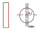 | ||
symmetry | Draws a centerline extending beyond the part and acting as a break line. 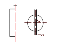 | ||
symmetry_iso | Displays a half view symmetry line according to ISO standard 128:1982 5.5— half view symmetry lines are displayed in yellow with thin linestyle, and the "hash" marks at the ends of the symmetry line are also yellow with thin linestyle. | ||
symmetry_asme | Displays a half view symmetry line according to ASME standard ASME Y14.2M-1992—half view symmetry lines are displayed in yellow with thin linestyle, and the "hash" marks are displayed in white with thick linestyle. | ||
none | Draws the object a small distance past the symmetry line. 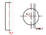
|
harn_tang_line_display
Controls the display of all the internal segment portions of cables when you display thick cables.
Default and Available Settings:
• no*—Does not display all the internal segments for thick cables.
• yes—Displays all the internal segments for thick cables.
• default—Reverts to the setting established with the harn_tang_line_display configuration file option.
Detail options that have configuration options of the same name only override the configuration setting within drawings. The configuration setting remains the same within the model. |
hidden_tangent_edges
Controls the display of hidden tangent edges in drawing views.
Default and Available Settings:
• default*—Reverts to the environment display setting for tangent edges.
• dimmed—Plots hidden tangent edges in a view using Pen 7. Lines appear dashed in same color as dimmed visible tangent edges. However, you must select Hidden Line or No Hidden Line from the Display Style list in the Environment dialog box that opens when you click > .
• erased—Removes all hidden tangent edges automatically from screen and plot.
hlr_for_datum_curves
Specify whether datum curves should be included for hidden line calculations.
Default and Available Settings:
• yes*—Datum curves are included when calculating the display of hidden lines. Blanking and unblanking datum curves on a drawing will cause hidden lines in views to be recalculated.
• no—Datum curves are not included when calculating the display of hidden lines. Blanking and unblanking datum curves on a drawing will not cause hidden lines in views to be recalculated. When using this option, datum curves will be displayed in wireframe.
Hidden lines are initially calculated for all views when this configuration option is changed. This ensures that the display of the drawing remains stable when saved and retrieved. Subsequent blanking and unblanking of layers containing only datum curves will not force hidden lines to be recalculated. |
hlr_for_pipe_solid_cl
Controls the display of pipe centerlines. This Detail option only operates on pipes created in Piping, not on pipe features in a part.
Default and Available Settings:
• no*—Hidden line removal does not affect pipe centerlines.
• yes—Hidden line removal affects pipe centerlines.
hlr_for_threads
Controls the display of threads in a drawing depending on whether it complies with the ISO, ANSI, or JIS standard set by the thread_standard Detail option.
Default and Available Settings:
• yes*—Thread edges meet ANSI, ISO, or JIS standard for Hidden Line display.
• no—Displays thread edges as surfaces as they would be in Part mode.
If you change the setting for the hlr_for_threads Detail option, then the drawing reflects the changes only after you update the drawing by clicking > > . |
hlr_multithreading
Controls whether the hidden line removal calculations take advantage of hardware with multiple cores or processors.
• yes*—Enables this capability to save significant time while updating views of complex models.
• no—Does not enable this capability.
ignore_model_layer_status
Controls display status of model layers within drawing environment.
• yes*—Ignores changes in model layers. The display status of common layers is controlled separately in the drawing. This option is not applicable to layers with special designation, such as Hidden Items and Shown Items.
• no—Considers model layer status. The display status of layers is controlled by the model.
• all—Ignores status of all model layers. The display status of layers is controlled separately in the drawing. This option is applicable to all layers, including high-level layers with special designation, such as Hidden Items, Shown Items, PIPING_BLANKED_LAYER, and so on.
intersected_lines_delta
Sets the default length of intersecting projected contours of outlines beyond the point of intersection. The default value is the value specified for the Detail option witness_line_delta.
iso_ordinate_delta
Improves display of offset between an ISO-ordinate dimension line and witness line, referred to as the witness line delta.
Default and Available Settings:
• no*—Does not display offset exactly in accordance with the specified value (it is "off" by about 2 millimeters).
• yes—Displays offset correctly, according to value specified for the Detail option witness_line_delta.
lead_trail_zeros
Controls the display of leading and trailing zeros in dimensions.
Default and Available Settings:
• std_default*—Displays trailing and leading zeros based on the model unit system. If you set the model units to Metric system, only the leading zeros appear ignoring the trailing zeros. Similarly, if you set the model units to English system, only the trailing zeros appear ignoring the leading zeros.
• std_metric—Displays only leading zeros. Trailing zeros are not displayed.
• std_english—Displays only trailing zeros. Leading zeros are not displayed.
• both—Both leading and trailing zeros are displayed.
• If the lead_trail_zeros_scope Detail option is set to all, the lead_trail_zeros Detail option controls the display of leading and trailing zeros in dimensions, hole parameters within hole notes, and all floating point parameters on a drawing, including parametric notes, view scale notes, tables, symbols, and cosmetic thread notes. • In case of dual dimensioning, the lead_trail_zeros Detail option controls the use of leading and trailing zeros in both std_english and std_metric standards independently. ◦ If the units in the dual_dimensioning Detail option are primary[secondary], std_english[std_metric] shows the primary units values with trailing zeros, while the secondary units show values with leading zeros. ◦ If the units in the dual_dimensioning Detail option are secondary[primary], std_english [std_metric] secondary units show values with trailing zeros, while the primary units show values with leading zeros. • Hole parameters within the hole notes appear with 3 decimals, regardless of the value set for the default_dec_places configuration option. If you want to change the number of decimal places for the hole parameter, type [.n] after the parameter in the Text tab of the Note Properties dialog box. Here, n is the number of decimal places. You can edit the hole parameter values only through the Note Properties dialog box that opens when you select the hole note and click > . Alternatively, to edit hole parameter values through the Note Properties dialog box, select the hole note, right-click, and click Edit Value on the shortcut menu. |
lead_trail_zeros_scope
Controls whether only dimensions are affected by the setting of the Detail option lead_trail_zeros.
Default and Available Settings:
• dims*—The Detail option lead_trail_zeros controls only dimensions.
• all—The Detail option lead_trail_zeros controls dimensions, hole parameters within hole notes and also all floating point parameters on a drawing, including parametric notes, view scale notes, tables, symbols, and cosmetic thread notes.
leader_elbow_length
Determines the length of the leader elbow for model and draft datums.
Specify a value to this option to:
• Set the default elbow length for new set datums
• Reset the elbow length for the existing set datums if you have not explicitly modified the elbow length of the existing set datums.
Default and Available Settings:
0.250000*
• The elbow length of a set datum is not controlled by leader_elbow_length Detail option, once you have explicitly modified the elbow length of a set datum. • The drawing_units Detail option determines the unit of measurement for the leader_elbow_length Detail option. |
leader_extension_font
Sets the font for leader extension lines for notes, surface finish symbols, and symbols. Leader extension lines are created when you drag a draft entity off its attachment.
The option does not apply to curved leader extensions. |
Default and Available Settings:
• SOLIDFONT*
• DOTFONT
• CTRLFONT
• PHANTOMFONT
• DASHFONT
• CTRLFONT_S_L
• CTRLFONT_L_L
• CTRLFONT_S_S
• DASHFONT_S_S
• PHANTOMFONT_S_S
• CTRLFONT_MID_L
• INTMIT_LWW_HIDDEN
• PDFHIDDEN_LINESTYLE
line_style_standard
Controls standard of line display in drawings.
Unless you set this option to std_ansi, all drawing text displays in blue, and the boundaries of detailed views display in yellow.
Default and Available Settings:
• std_ansi*—Applies American National Standards Institute (ANSI)
• std_iso—Applies International Organization for Standardization (ISO)
• std_jis—Applies Japanese Industrial Standard (JIS)
• std_din—Applies Deutsches Institut für Normung (DIN) (German Institute for Standardization)
line_style_length
Sets the font length for sketched entities.
Default and Available Settings:
• font_name_default*—Indicates default length values, enter the font name and then a desired value for the font length in system units.
• font_name value—Enter the font name and then a desired value for the font length in system.
location_radius
Modifies radius of nodes indicating location, improving their visibility, particularly when printing drawings.
Default and Available Settings:
• default (2.)*—Sets radius as 2 drawing units.
• 0.0—Displays location nodes, but does not print them. There is no maximum value for this setting. You can type a value for the radius of nodes indicating location.
The drawing_units Detail option determines the unit of measurement for the location_radius Detail option. |
max_balloon_radius
Sets the maximum allowable balloon radius.
Default and Available Settings:
• 0.000000*—Balloon radius depends only on text size. You can type a value for the maximum allowable balloon radius.
The drawing_units Detail option determines the unit of measurement for the max_balloon_radius Detail option. |
mesh_surface_lines
Controls display of blue surface mesh lines.
Default and Available Settings:
• on*—Blue surface mesh lines display.
• off—Blue surface mesh lines do not display.
min_balloon_radius
Sets minimum allowable balloon radius.
Default and Available Settings:
• 0.000000*—Balloon radius depends only on text size. You can type a value for the minimum allowable balloon radius.
The drawing_units Detail option determines the unit of measurement for the min_balloon_radius Detail file option. |
min_dist_between_bom_balloons
Controls the default minimum distance between BOM balloons.
Default and Available Settings:
• 0.800000*
minimum_angle_dimension
Specifies the minimum angle value at which selected dimension references are not considered parallel.
Default and Available settings:
• The default value changes based on the Creo Parametric version in which the drawing is created.
If you open a drawing created in Creo Parametric 4.0 M070 and earlier, the default value is follow_config, meaning the default value is as specified in the configuration option minimum_angle_dimension.
If you open a drawing created in Creo Parametric 4.0 M080 and later, the default value is 1.
• You can specify a different value.
For example, you can specify 4 as the value for this Detail option. If the angular value between the references is 3, a linear dimension is created between the references. If the angular value between the references is 5, an angular dimension is created between the references.
model_digits_in_region
Controls display of number of digits in two-dimensional repeat regions.
Default and Available Settings:
• yes*—Two-dimensional repeat regions reflect the number of digits of part and assembly model dimensions.
• no—Two-dimensional repeat region digits are independent of the part and assembly model dimension settings.
model_display_for_new_views
Specifies the display style for drawing views.
Default and Available Settings:
• default*—Reverts to the environment setting. The environment is determined by the setting in the Display Style box in the Environment dialog box that opens when you click > .
This is the default model display only for views imported from Pro/ENGINEER Wildfire 2.0 and earlier. You can set this configuration option to the default setting or to the other settings supported for the current release. As a result, the drawings become valid for the current release. |
• follow_environment*—Always follow the current setting in the environment at the time of view creation.
This is the default setting for drawing views created in Pro/ENGINEER Wildfire 3.0. |
• wireframe—Displays the view in wireframe.
• hidden_line—Displays the view with hidden lines.
• no_hidden—Displays the view without showing hidden lines.
• shading—Displays the view in shading, taking the colors from the model.
• save_environment—Saves the current environment setting for newly created views within the drawing. If the environment setting changes, the view is not updated.
If you set the enable_shaded_view_in_drawing configuration option to no and the model_display_for_new_views Detail option to shading, then the actual display of the drawing view is in wireframe. |
model_grid_balloon_display
Determines whether a circle will be drawn around the model grid text.
Default and Available Settings:
• yes*—Draws a circle around the model grid text.
• no—Does not draw a circle around the model grid text.
model_grid_balloon_size
Specifies the default radius of balloons shown with the model grid in a drawing.
Default and Available Settings:
0.200000*
The drawing_units Detail option determines the unit of measurement for the model_grid_balloon_size Detail option. |
model_grid_neg_prefix
Controls prefix of negative values shown in model grid balloons.
model_grid_num_dig_display
Controls number of digits displayed in grid coordinates that appear in grid balloons.
Default and Available Settings:
• 0*—The system default (0) to display coordinates as integers. You can type a value for the number of digits displayed in grid coordinates.
model_grid_offset
Controls offset of new model grid balloons from the drawing view.
Default and Available Settings:
• default*—Offsets new model grid balloons from the drawing view by twice the current model grid spacing. You can type a value for the offset of model grid balloons from the drawing.
The drawing_units Detail option determines the unit of measurement for the model_grid_offset Detail option. |
model_grid_text_orientation
Determines whether the model grid text orientation will be parallel to the grid lines or always horizontal.
Default and Available Settings:
• horizontal*—Always displays the model grid text horizontal to the grid lines.
• parallel—Displays the model grid text parallel to the grid lines.
model_grid_text_position
Determines whether the model grid text will appear above, below, or centered about the grid line.
Default and Available Settings:
• centered*—Centers the model grid text about the grid line.
• above—Places the model grid text above the grid line.
• below—Places the model grid text below the grid line.
If you set the model_grid_text_orientation Detail option to horizontal, model_grid_text_position is ignored. |
modify_driving_dim_by_precision
Controls the modification of driving dimension when you update the precision value.
• yes*—Modifies the dimension value causing the model regeneration.
• no—Modifies only the number of digits the dimension will display.
Consider an example when a dimension has a value of 0.1234 with 4 digits of precision. Now you modify the precision value to 3 digits.
When the modify_driving_dim_by_precision Detail option is set to yes, the dimension value is changed to 0.123 and the model is regenerated. When the Detail option is set to no the value of the dimension is displayed as 0.123, but the feature retains the value 0.1234 therefore the model is not regenerated. In both cases, the model is modified by the change in digits operation.
new_iso_set_datums
Controls display of set datums according to ISO standards.
Default and Available Settings:
• yes*—Displays set draft datums according to ISO standards.
• no—Does not display set draft datums according to ISO standards.
node_radius
Controls display of nodes in symbols.
Default and Available Settings:
• default*—Specifies the default radius of the nodes. You can type a value for the radius of nodes within symbols. If the setting is so small that the nodes do not appear, the system uses the default setting. There is no maximum value for this setting.
The drawing_units Detail option determines the unit of measurement for the node_radius Detail option. |
ord_dim_standard
Controls the display standard for ordinate dimensions in your drawing.
The ord_dim_standard Detail option works in conjunction with the following Detail options:
• draw_arrow_style—Sets the arrow style to closed, open, or filled.
• draw_dot_diameter—Sets the diameter for the leader line dots (the circle on the baseline).
Default and Available Settings:
std_ansi* | Places related ordinate dimensions without a connecting line. | 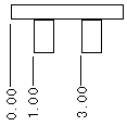 |
std_iso | Displays ordinate dimensions in the International Organization for Standardization (ISO) format. | 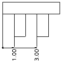 |
std_jis | Places related ordinate dimensions along the connecting line perpendicular to the baseline and starts with an open circle. Each segment of the connecting line ends with an arrow. | 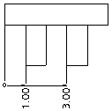 |
std_din | Displays ordinate dimensions in the Deutsches Institut für Normung (DIN) (German Institute for Standardization) format. |  |
same_as_3d | Displays ordinate dimensions of a 3D model in the same style as they appear in the drawing. |
• When ord_dim_standard is set to std_jis, the end circle will always be an open circle with a fixed size regardless of the values of draw_dot_diameter and draw_arrow_style. • When witness lines are interconnected, moving any of the related dimensions moves all the dimensions. |
ord_dim_origin_style
Sets the style of origin for ordinate dimensions when detail setup option ord_dim_standard is set to std_iso or std_din.
Default and Available Settings:
• empty*—Origin for ordinate dimensions appears empty.
• filled—Origin for ordinate dimensions appears filled.
pipe_insulation_solid_xsec
Determines whether the insulation in the pipe cross section is displayed as a solid (filled) region.
Default and Available Settings:
• no*—Pipe insulation cross sections are not displayed as solid regions.
• yes—Pipe insulation cross sections are displayed as solid regions.
This option does not apply to offset cross sections. |
pipe_pt_line_style
Controls the line style of a theoretical bend intersection point that appears within the shape defined by the pipe_pt_shape Detail option in a piping drawing.
Default and Available Settings:
• default*—The bend intersection point appears with a default line style.
• phantom—The bend intersection point appears with a phantom line style.
• solid—The bend intersection point appears with a solid line.
pipe_pt_shape
Controls shape of theoretical bend intersection points in a piping drawing.
Default and Available Settings:
• cross*
• dot
• circle
• triangle
• square
pipe_pt_size
Controls size of theoretical bend intersection points in a piping drawing.
Default and Available Settings:
• default*—Specifies the default size of theoretical bend intersection points. You can type a value for the size of theoretical bend intersection points in piping drawings.
The drawing_units Detail option determines the unit of measurement for the pipe_pt_size Detail option. |
pos_loc_format
Controls the appearance of &pos_loc text both in notes and report tables. The character pairs %% are used in the following ways:
• %s indicates single sheet
• %x and %y indicate the horizontal and vertical positions
• %r indicates the end of a repeatable substring
Default and Available Settings:
Type the desired character pairs to determine the appearance of &pos_loc text, such as %s%x%y, %r*.
projection_type
Determines method for creating projection views.
Default and Available Settings:
• third_angle*
• first_angle
proj_view_note_format
Defines the format for projection view notes.
Default format if the view_note option in the Detail option file is set to std_din is <viewname>-<viewname>, else it is VIEW <viewname>-<viewname>. Alternatively, type a view label in the format View %viewname, %viewname.
ptc_reported_material_in_region
Specifies what to show in the repeat region when the PTC_REPORTED_MATERIAL parameter contains values of multiple materials.
• multi-material*—Shows the string MULTI-MATERIAL in the repeat region.
• list—Shows a list of materials assigned to all the bodies in the part.
• empty—Shows an empty cell.
This option is applicable only when you use the &mdl.body.ptc_material.PTC_REPORTED_MATERIAL report symbol to display the material information in the repeat region. |
radial_dimension_display
Allows display of radial dimensions in ASME, ISO or JIS standard formats, except when the dimension appears using Horizontal (ASME) format of the text orientation. This affects the style of the arrow attached to the centerline for the radial dimensions that appear in linear format.
Use this Detail option with the default_raddim_text_orientation Detail option for setting the display of radial dimensions. |
Default and Available Settings:
• std_asme—Displays radial dimensions in the American Society of Mechanical Engineers (ASME) format
• std_iso—Displays radial dimensions in the International Organization for Standardization (ISO) format
• std_jis—Displays radial dimensions in the Japanese Industrial Standard (JIS) format
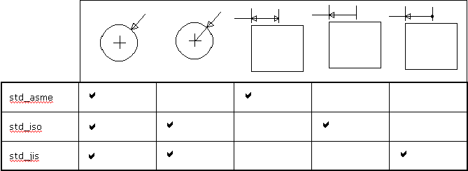
radial_pattern_axis_circle
Sets display mode for axes of rotation that are perpendicular to the screen in radial pattern features.
Default and Available Settings:
no* | Displays the individual axis lines. 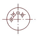 |
yes | A circular shared axis appears, and axis lines pass through the center of a rotational pattern. 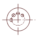 |
reference_bom_balloon_text
Controls reference balloon text identifier for BOM balloons. The value of this Detail option appears next to the balloon for simple balloons and in place of the quantity value for quantity balloons.
Default and Available Settings:
• REF*—Text string REF appears next to the balloon for simple balloons. For quantity balloons, the string REF appears instead of the quantity value.
• <user-defined text>—User-defined text string appears next to the balloon for simple balloons. For quantity balloons, the user-defined text string appears instead of the quantity value.
remove_cosms_from_xsecs
Controls the display of datum curves, threads, cosmetic feature entities, and cosmetic cross-hatching in a full cross-sectional view.
Default and Available Settings:
• trim*—Cuts away parts of features in front of the cutting plane.
• total/yes—Removes features located entirely in front of the cutting plane from the cross-sectional view. Displays these features in full only if they intersect the cutting plane. This setting is applicable only for full cross-sectional views and does not apply to view that has combination of cross section types.
• all—Removes datums and cosmetics from all types of cross-sectional views.
• none/no—Displays all datum quilts and cosmetic features.
set_datum_leader_length
Determines the default length of the leader for a draft set datum and model set datum.
Default and Available Settings:
0.375000
• The drawing_units Detail option determines the unit of measurement for the set_datum_leader_length Detail option. • For drawings created in releases prior to Pro/ENGINEER Wildfire 4.0, the default length of the leader for draft set datum and model set datum is 1.5 times the value of the leader_elbow_length Detail option. |
set_datum_triangle_display
Controls the display of the set datum triangle as an empty triangle or a filled triangle, in both draft and model set datum labels. Changing the value of the configuration option results in the change of display of all set datum triangles in the current drawing. You cannot change the display of individual datum triangles.
Default and Available Settings:
• filled*—The set datum triangle is filled.
• open—The set datum triangle is not filled.
This Detail option does not affect the three-dimensional model. |
shaded_view_scene
Controls the use of scene for shaded drawing views.
• drawing*–Use the fixed light and scene settings. This setting does not change the appearance of the shaded view.
• model–Use the scene, if present, that is defined in the 3D model that corresponds to the shaded view. Alternatively, use the Creo default scene.
show_cbl_term_in_region
Allows use of the report symbols &asm.mbr.name and &asm.mbr.type to show terminators in Pro/REPORT tables for cable assemblies having connectors with terminator parameters.
Default and Available Settings:
• no*—For existing drawings, the default value is no.
• yes—Shows terminators. You must set the attribute Cable Info for the repeat region. When creating new drawings, the default value is yes.
show_clipped_dimensions
Determines whether to display dimensions with clipped references in a limited visibility view (partial, broken, half, detail).
• no*—Dimensions are shown as erased and they cannot be unerased.
• yes—Dimensions are displayed and they can be erased manually, as desired.
show_dim_sign_in_tables
Controls the display of negative values in a drawing table for drawing items with negative values in a Family Table.
Default and Available Settings:
• yes*—Displays negative values in a drawing table.
• no—Does not display negative values in a drawing table.
yes is the default setting only for newly created drawings. For existing drawings, the default setting is no. Set the value of show_dim_sign_in_tables to yes to display negative signs for existing drawings. |
show_pipe_theor_cl_pts
Controls display of centerlines and theoretical intersection points in piping drawings.
Default and Available Settings:
• bend_cl*—Shows centerlines with bends only.
• theor_cl—Shows only centerlines with theoretical bend intersection points.
• both—Shows both bends and theoretical intersection points.
show_quilts_in_total_xsecs
Determines if surface geometry is included in a drawing cross section and whether the surface will be cut by the cross section cutting plane.
Surface geometry (surfaces and surface quilts) will only be cut by the cross-section cutting plane in a drawing view when the cross-section is created in part or assembly mode. If the cross-section is created as a Model (default), the surface geometry will not be cut by the cutting plane.
Default and Available Settings:
• no*—Exclude surface geometry.
• yes—Include surface geometry.
show_offset_section_seams
Controls the display of the seam that exists between segments of an offset section. This option is not applicable to the Full(Unfold) and Full(Aligned) views.
• angled_only*—Seam is shown for segments at angles other than 90 degrees.
• all—Seam is shown for all segments including perpendicular segments.
• none—Seam is not shown for any segment.
show_total_unfold_seam
Controls display of seams (the edges of the cutting plane) in total unfolded cross-sectional views.
Default and Available Settings:
yes* | Displays the seams (the edges of the cutting plane).  |
no | Blanks the seams (the edges of the cutting plane).  |
shrinkage_value_display
Displays dimension shrinkage in percentages or as final values.
Default and Available Settings:
• percent_shrink*
• final_value
smt_bend_line_axis_style
Defines the line style of axes representing sheetmetal bending lines. By default, if you do not customize a line style of axes, it is displayed in default axis font. You can also select dashed or solid font or set the font to be bend direction-dependent, so custom line style is ignored.
Default and Available Settings:
• default*—When you manually define line style of axes, it is displayed in the same font, regardless of the bend direction. When you did not specify any custom line style, the axis is displayed using the default axis font.
• ctrlfont —The bend axis is always displayed using the dashed font regardless of the bend direction.
• solidfont—The bend axis is always displayed using the solid font regardless of the bend direction.
• bend_direction—The font of the bend axis depends on the bend direction, solid (for upward direction) and dashed (for downward direction). In this case, the font is sensitive to changing the view orientation (for example, changing view orientation from back to front).
sort_method_in_region
Determines the sorting mechanism for repeat regions.
Consider the following examples:
Value | Description | Example |
|---|---|---|
delimited* | Logically evaluates sections between delimiters. The supported delimiters are as follows: ‘ ’, ‘-’, and ‘_’ | 01-10 1-10 1-20 02-10 2-10 2-20 03-05 03-5 0A-01 0A-1 0A-02 0B-01 |
string_only | Sorts alphabetically. | 01-10 02-10 03-05 03-5 0A-01 0A-02 0A-1 0B-01 1-10 1-20 2-10 2-20 |
trailing_numbers | Logically evaluates trailing numbers. For example, 1 > 02. | 01-10 02-10 03-05 03-5 0A-01 0A-1 0A-02 0B-01 1-10 1-20 2-10 2-20 |
pre–2001 | Reverts to pre-2001 sort mechanism. | - |
stacked_gtol_align
Controls the alignment of the control frame for stacked geometric tolerances.
The geometric tolerance stack control frame is always centered on the attached leader line.
Default and Available Settings:
• yes*—Geometric tolerances comply with the JIS standard; alignment on both ends of the control frame.
• no—The controls frames do not align.
Unaligned Control Frames | Aligned Control Frames |
|---|---|
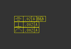 | 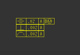 |
substituted_comp_cparam_report
Defines the parameters that are in the report for the repeat region after substituting a component by a family table instance, or a different representation state.
• original*—Reports parameters from the original component.
• substitute—Reports parameters from the substituting component.
sym_flip_rotated_text
Flips any text in a rotate text symbol that is upside down, making it right-side up.
Default and Available Settings:
• no*—Does not flip the text.
• yes—If the symbol orientation is +/- 90 degrees, flips the text, rotating it along with the symbol.
symbol_font
Defines the font used for symbols available within Creo annotations
Default and Available Settings:
• asme*—Provides the ASME symbols in TrueType font in the text symbol palette .
• iso—Provides the ISO symbols in TrueType font in the text symbol palette .
• legacy—Provides the legacy symbols in the text symbol palette in the font native to Creo.
• stroked_asme—Provides the same set of symbols as the ASME value, but in the font native to Creo.
• stroked_iso—Provides the same set of symbols as the ISO value, but in the font native to Creo.
symmetric_tol_display_standard
Controls the display standard of symmetric tolerances.
Default and Available Settings:
• std_asme*—Applies American Society of Mechanical Engineers (ASME)
• std_din—Applies Deutsches Institut für Normung (DIN) (German Institute for Standardization)
• std_iso—Applies International Organization for Standardization (ISO)
tan_edge_display_for_new_views
Specifies the tangent edge display.
Default and Available Settings:
• default*—Displays tangent edges according to the setting in the Environment dialog box ( > ).
• tan_solid—Displays selected tangent edges regardless of the environment setting for tangent edges.
• no_disp_tan—Turns off the display of tangent edges.
• tan_ctrln—Displays tangent edges in centerline font.
• tan_phantom—Displays tangent edges in phantom font.
• tan_dimmed—Displays tangent edges in dimmed color.
• save_environment—Saves and uses the environment setting for newly created views within the drawing.
text_height
Sets the default text height for newly created annotations.
Default and Available Settings:
0.156250*
text_thickness
Sets default text thickness for new text after regeneration and existing text whose thickness has not been modified. Type the value in drawing units.
Default and Available Settings:
• 0.000000*
• 0<value<.5
text_width_factor
Sets default ratio between the text width and text height. The system maintains this ratio until you change the width using the Text Width command.
Default and Available Settings:
• 0.800000*
• 25<#>0.8
thread_standard
Controls the display of threaded holes with an axis perpendicular to the screen as an arc (ISO standard), or as a circle (ANSI standard), or the hidden lines inside the threaded holes (JIS Standard).
Default and Available Settings:
• std_ansi*—Displays the threaded holes in accordance with the ANSI standard.
• std_ansi_imp—Does not display hidden thread lines when you select No Hidden Line from the Display Style list in the Environment dialog box that opens when you click > . When you select Hidden Line, thread lines are displayed as leader lines (yellow).
• std_ansi_imp_assy—Displays threaded holes in accordance with the ANSI standard.
• std_iso—Displays threads in cross-sectional assembly drawings in accordance with the ISO 6410 standard.
• std_iso_imp—Does not display hidden thread lines when you select No Hidden Line from the Display Style list in the Environment dialog box that opens when you click > . When you select Hidden Line, thread lines are displayed as leader lines (yellow).
• std_iso_imp_assy—Displays threads in cross-sectional assembly drawings in accordance with the ISO 6410 standard.
• std_jis—Displays threads in the top and side views of drawings in accordance with the JIS standard.
The std_iso and std_ansi values are valid for drawings created before Pro/ENGINEER Release 15.0. |
tol_display
Controls display of dimension tolerances.
Default and Available Settings:
• no*—Does not display dimension tolerances.
• yes—Displays dimension tolerances.
• no_tol_tables—Does not display dimension tolerances for tolerances that are controlled by ISO tolerance tables.
Detail options that have configuration options of the same name only override the configuration setting within drawings. The configuration setting remains the same within the model. |
tol_text_height_factor
Sets the default ratio between the dimension text height and the tolerance text height when showing the tolerance in plus-minus and +- symmetric formats. |  1. Dimension text height 2. Tolerance text height |
Default and Available Settings:
• standard*—Creo Parametric uses 1 for the ANSI standard and .6 for the ISO standard. You can specify a value greater than zero.
When you show the tolerance in a plus-minus format for a dimension with ISO standard, if you set the value of this Detail option as the default value (standard), the ratio between the tolerance text height and the dimension text height is 0.6, in the following cases: • The dimension has parallel orientation. • The dimension has the default orientation. However, the text orientation is set as parallel using its corresponding Detail option. For example, for a linear dimension with default orientation, the value of the default_lindim_text_orientation is set as parallel_to_and_above_leader or parallel_to_and_below_leader. |
Set the value of this Detail option as 1 so that the tolerance text height is the same as the dimension text height for dimensions with parallel orientation.
tol_text_width_factor
Sets the default factor to maintain a proportion between the dimension text width and the tolerance text width when showing the tolerance in plus-minus and +- symmetric formats. |  1. Dimension text width 2. Tolerance text width |
Default and Available Settings:
• standard*—Creo Parametric uses .8 for the ANSI standard and .6 for the ISO standard. You can specify a value greater than zero.
use_major_units
Controls whether fractional dimensions are displayed in feet-inches within drawings.
This Detail option supersedes the configuration file option of the same name (use_major_units) unless the Detail option is set to default.
Default and Available Settings:
• default*—Displays fractional dimensions according to the setting of the configuration file option use_major_units.
• yes—Fractional dimensions are displayed in major units.
• no—Fractional dimensions are not displayed in major units.
Detail options that have configuration options of the same name only override the configuration setting within drawings. The configuration setting remains the same within the model. |
view_note
Determines the standard text requirements for view-related notes.
Default and Available Settings:
• std_ansi*, std_iso, std_jis, std_gb, and std_eskd—Creates a view-related note with standard references, such as SEE DETAIL.
• std_din—Creates a view-related note with the words "SECTION," "DETAIL," and "SEE DETAIL" omitted.
If you switch the setting from std_ansi, std_iso, std_jis, std_gb, or std_eskd to std_din, the view related notes do not update. |
If you set the value of the view_note Detail option to std_gb, use the default_view_lable_placement Detail option to control the alignment of the view note text. |
view_scale_denominator
Determines denominator for the view scale before simplifying the fraction.
Default and Available Settings:
• 0*—The default is 0. You can specify a different value, if required.
If set to a positive integer and view_scale_format is a decimal, the view scale chosen for the first view of a model in the drawing is rounded to the nearest value with the specified denominator. If the view scale is so small that rounding would make the scale 0.0, the value of view_scale_denominator is automatically changed by multiplying it by the smallest power of 10, which would give a positive value if rounding the scale down (although rounding up can happen). When you type a view scale value, you can round it to an allowable fraction. The system does not round existing scale values after you have edited the setup file; they are approximate. Displays approximate scales preceded by a tilde (~), if you set the configuration file option mark_approx_dims to yes. If you set it to 0, expresses the scale value in decimal format. |
view_scale_format
Formats the drawing and view scale ratio.
Default and Available Settings:
• decimal*—Expresses the scale value as decimals.
• fractional—Expresses the scale value as fractions.
• ratio_colon—Displays the scale values as a ratio. For example, instead of the scale value of 0.5, displays the scale value as 1:2. Since the ratio is just another way of displaying a fraction, make sure that you set the view_scale_denominator Detail option appropriately.
• ratio_colon_normalized—Displays the scale value as a ratio that is normalized to have 1 as the numerator for scale less than 1:1, and 1 as denominator for scale greater than 1:1, as follows:
◦ For scale less than 1:1—The numerator appears as 1 and the denominator appears as the value that you set for the scale. For example, 1:2, 1:12, 1:2.5.
◦ For scale greater than 1:1—The denominator appears as 1 and the numerator appears as the value that you set for the scale. For example, 2:1, 10:1, 2.5:1.
With the ratio_colon_normalized setting, some scale values can result in either the numerator or the denominator to appear as a decimal value, without the trailing zeros, and rounded to maximum of three decimal places. For example, with the ratio_colon_normalized setting, a scale value of 2:3 will appear as 1:1.5. |
weld_light_xsec
Determines whether lightweight weld cross-section is shown.
Default and Available Settings:
• no*—Does not determine if lightweight weld cross-section is shown.
• solid_based
• circle
weld_solid_xsec
Determines if weld in cross section displays as solid (filled) region.
Default and Available Settings:
• no*—Weld cross sections do not display as solid regions.
• yes—Weld cross sections display as solid regions.
This Detail option does not apply to offset cross-sections. |
weld_spot_side_significant
Set up placement of Weld Spot symbol for ANSI/AWS2.4 norm.
Default and Available Settings:
• yes*
• no
weld_symbol_standard
Controls the standard display for weld symbols in a drawings.
Default and Available Settings:
• std_ansi*—Applies the American National Standards Institute (ANSI).
• std_iso—Applies International Organization for Standardization (ISO).
witness_line_delta
Sets the extension distance of the witness line (1) from the dimension leader arrow. |  |
Default and Available Settings:
• 0.125000*—The default value is 0.125000. You can specify a different value for the distance between the witness line and dimension leader arrow.
The drawing_units Detail option determines the unit of measurement for the witness_line_delta Detail option. |
witness_line_intersection
Determines if intersection witness lines will be enabled for new dimensions that reference entity intersections. This Detail option does not affect existing dimensions.
Default and Available Settings:
• no*—Disables intersection witness lines for new dimensions.
• yes—Enables intersection witness lines for new dimensions.
witness_line_offset
Sets offset between (1) a dimension line and object being dimensioned. It also determines the offset for: • Intersection witness lines of new dimensions. • Intersection witness lines of existing dimensions that are not modified. |  |
The offset may only be visible when you plot a drawing. To see the effect, use the screen plot.
Default and Available Settings:
• 0.062500*—The default is 0.62500. You can specify a different value for the offset between the dimension line and the object being dimensioned.
• The drawing_units Detail option determines the unit of measurement for the witness_line_offset Detail option. • To create intersection witness lines without a gap, specify the offset value as zero. • When you specify an offset value greater than the distance between the end of the intersection entity and the intersection, the length of the intersection witness line becomes zero as shown in the following figure: 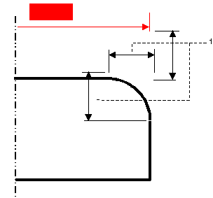 1. Witness line offset |
yes_no_parameter_display
Controls display of yes/no parameters in drawing notes and tables.
Default and Available Settings:
• true_false*—Parameters can have a "true" or "false" value.
• yes_no—Parameters can have a "yes" or "no" value in drawing notes.
zero_quantity_cell_format
Specifies the character to use in repeat regions cells that report a quantity of zero.
Default and Available Settings:
• empty*—No character is displayed in the cell.
• 0—The character ‘0’ is displayed in the cell.
• ‘-’—The character ‘-’ is displayed in the cell.