User-Defined Parametric Weld Symbols
You can replace the Creo Parametric-supplied library of system weld symbols with user-defined ones. After you define the symbols, the system uses them for automatic weld annotation. By customizing your weld symbols in advance, you can increase your flexibility and productivity throughout the processes of creating and modifying drawings.
|
|
Before performing this procedure, you should copy the system-supplied welding symbol library to a backup directory.
|
However, when creating user-defined weld symbols, the following restrictions apply:
• All of the groups that existed in the original definition must remain in the new definition, and you cannot add new ones or change the names of existing ones.
• If you add new variable text, or change the name of an existing piece of variable text, the new name must be the same as that of the existing variable text in the original.
• The height type of the symbol instance must be the same in the new user-defined symbol as it was in the original.
• The Left Leader and Right Leader placement types must both exist in the new user-defined weld symbol.
ISO Welding Symbols
This section presents examples of symbols that enable you to create welding, brazing, and examination symbols in a drawing according to the ISO standard. To help you create symbol instances, it provides the following information for each symbol:
• The symbol name
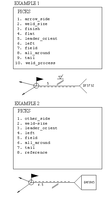
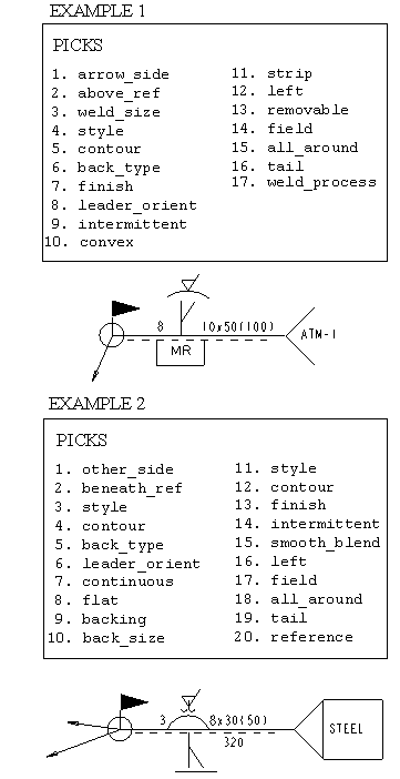
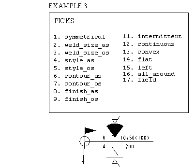
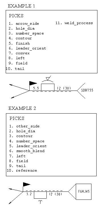
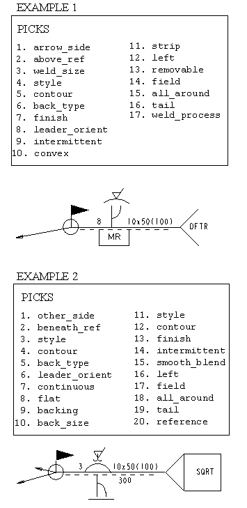
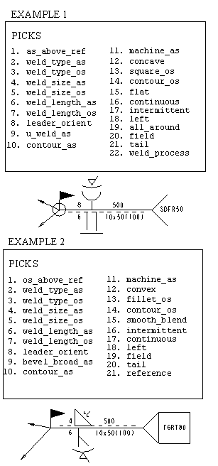
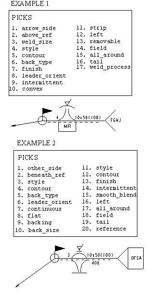
• An example of an instance created from this symbol and the associated menu picks
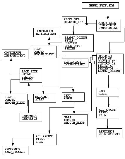
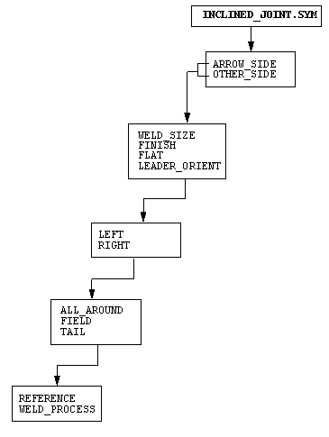
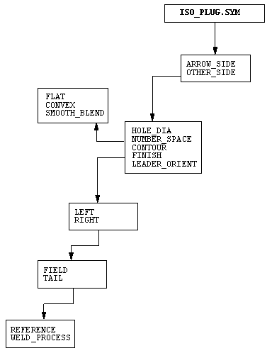
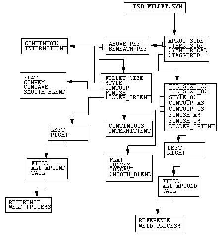
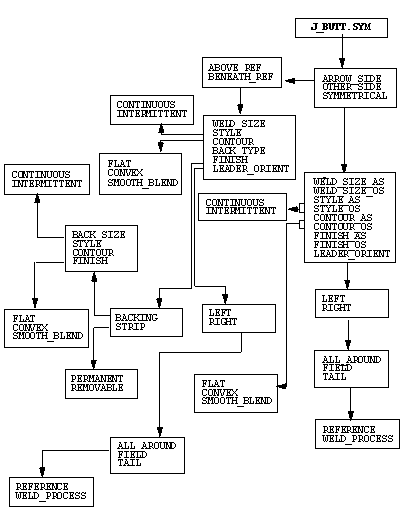
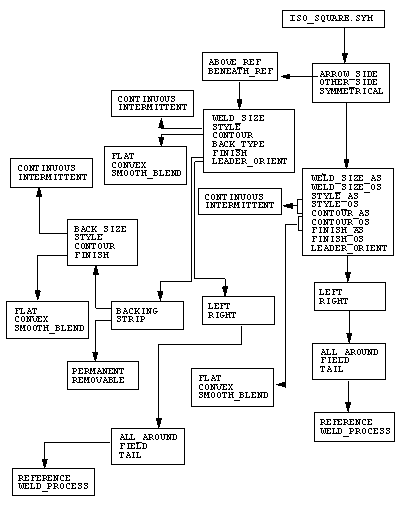
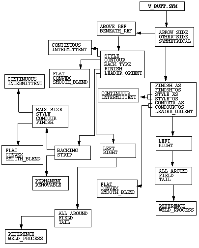
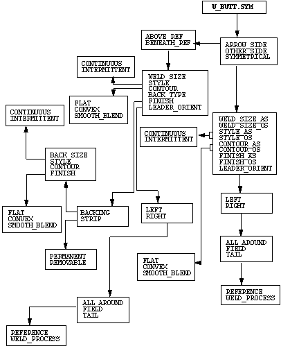
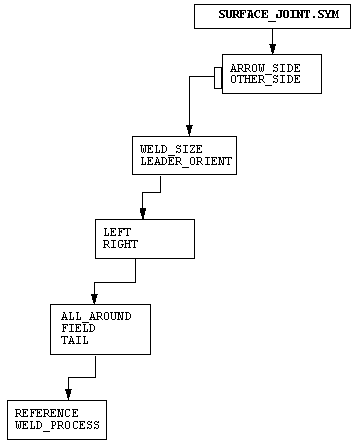
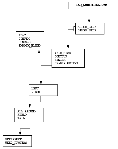
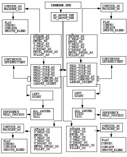
• Listings of groups and subgroups in menu format reflecting a tree symbol definition structure
You can also refer to Glossary of Menu Picks below for an explanation of menu selections for welding symbols.
Welding Symbols Library
The Welding Symbols Library, available with Detailed Drawings, provides a collection of symbols based on the standards of ISO-2553-1984. Using this library, you can create a variety of welding, brazing, and examination symbols in a drawing.
To retrieve a symbol from the Welding Symbol Library, choose System Syms from the Select File menu to access the Creo Parametric symbols area.
Glossary of Menu Picks
This glossary describes terms that are unique to the ISO Welding Symbol Library and identifies information you are prompted to enter. Menu pick names track the ISO Welding Symbol Library to the fullest extent possible.
In the ISO Welding Symbol Library, two lines form the reference line, one solid and one dashed. Weld symbols attached to the solid line are "arrow-side." Weld symbols attached to the dashed line are "other-side." The dashed line is only omitted for symmetrical welds. When creating a welding symbol, you first select whether the weld is arrow side, other-side, or symmetrical. If you choose ARROW_SIDE or OTHER_SIDE, the system prompts you to create the weld symbol above or beneath the reference line. It then places the dashed line appropriately in the symbol depending on whether it is arrow-side or other-side.
|
MENU PICK
|
OPTION
|
DESCRIPTION
|
|---|---|---|
|
ABOVE_REF
|
Creates the weld symbol above the solid reference line.
|
|
|
AS_ABOVE_ REF
|
Indicates (for combination welding symbols only) whether the arrow-side welding symbol is placed above or beneath the reference line.
|
|
|
BENEATH_REF
|
Creates the weld symbol beneath the solid reference line.
|
|
|
BUTT_SIZE
|
Refers to the final size of the weld, depending on the symbol type (arrow-side, other-side, symmetrical, or staggered). It might have the suffix "AS" (arrow-side) or "OS" (other-side) to indicate the appropriate weld side.
|
|
|
CONTOUR
|
SMOOTH_BLEND
|
Describes the final shape of the weld. This choice indicates that the toes of the weld are blended smoothly.
|
|
FINISH
|
In the ANSI standard, this specifies the method of finishing. In the ISO standard, the system adds a machine finish surface texture symbol above the contour symbol.
|
|
|
FILLET_SIZE
|
Refers to the final size of the weld, depending on the symbol type (arrow-side, other-side, symmetrical, or staggered). It might have the suffix "AS" (arrow-side) or "OS" (other-side) to indicate the appropriate weld side.
|
|
|
FIL_SIZE
|
Refers to the final size of the weld, depending on the symbol type (arrow-side, other-side, symmetrical, or staggered). It might have the suffix "AS" (arrow-side) or "OS" (other-side) to indicate the appropriate weld side.
|
|
|
HOLE_DIA
|
Refers to the diameter of a plug weld.
|
|
|
OS_ABOVE_ REF
|
Indicates (for combination welding symbols only) whether the other-side welding symbol is placed above or beneath the reference line.
|
|
|
PROJECT_DIA
|
Refers to the diameter of a projection weld.
|
|
|
SEAM_WIDTH
|
Refers to the width of a seam weld.
|
|
|
SPOT_DIA
|
Refers to the diameter of a spot or fusion weld.
|
|
|
STYLE
|
CONTINOUS
INTERMITTENT
|
Refers to the longitudinal dimension of a weld. Two choices are available:
Weld joint continuously for the specified length.
Creates weld beads of specified length, distance between adjacent weld elements, and specific number of beads.
|
|
SYMMETRICAL
|
Refers to a welding symbol for creating identical welds on both arrow-side and other- side.
|
|
|
TAIL
|
REFERENCE
WELD_PROCESS
|
Creates a tail on the opposite end of the welding symbol from the leader attachment. Provides two choices:
Enters reference text or note.
Specifies a welding process.
|
|
WELD_SIZE
|
Refers to the final size of the weld, depending on the symbol type (arrow-side, other-side, symmetrical, or staggered). It might have the suffix "AS" (arrow-side) or "OS" (other-side) to indicate the appropriate weld side.
|
|
|
WELD_TYPE
|
For combination welding symbols, indicates the type of weld being created and whether it is created arrow-side or other-side (e.g., FILLET_AS).
|
Bevel Butt Symbol: Bevel_Butt.sym
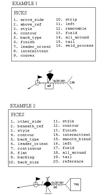
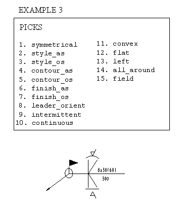
Symbol Definition Structure
Inclined Joint Symbol: Inclined_Joint.sym
Symbol Definition Structure
Bevel Butt with Broad Root Face: Br_Root_Bevel.sym
Symbol Definition Structure
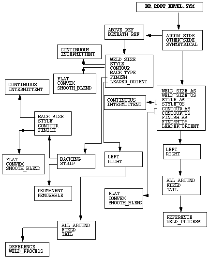
Slot Symbol: Iso_Slot.sym
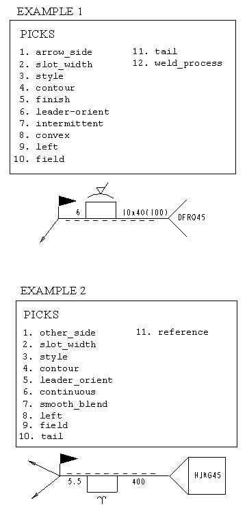
Symbol Definition Structure
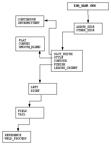
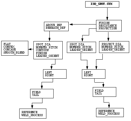
Spot Symbol: Iso_Spot.sym
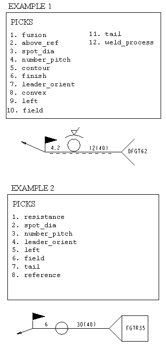
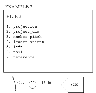
Symbol Definition Structure
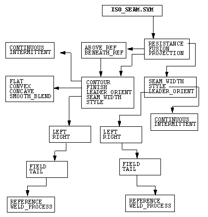
Seam Symbol: Iso_Seam.sym
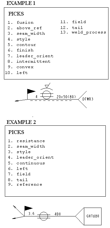
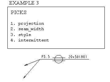
Symbol Definition Structure
Plug Symbol: Iso_Plug.sym
Symbol Definition Structure
Fillet Symbol: Iso_Fillet.sym
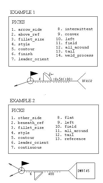
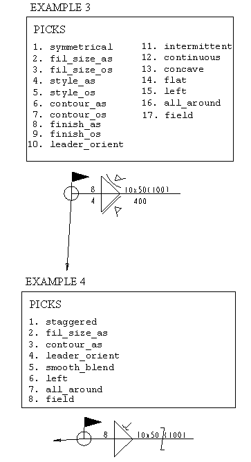
Symbol Definition Structure
J Butt Symbol: J_Butt.sym
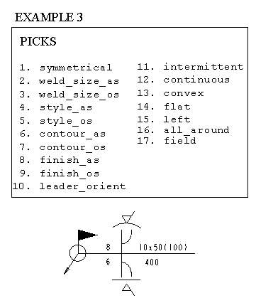
Symbol Definition Structure
Square Butt Symbol: Iso_Square.sym
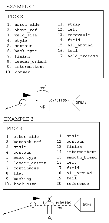
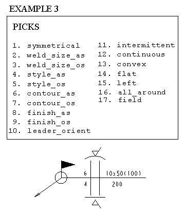
Symbol Definition Structure
V Butt Symbol: V_Butt.sym
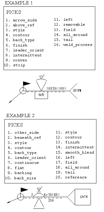
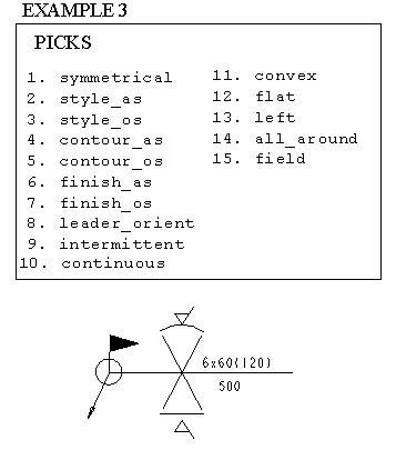
Symbol Definition Structure
U Butt Symbol: U_Butt.sym
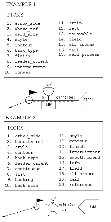
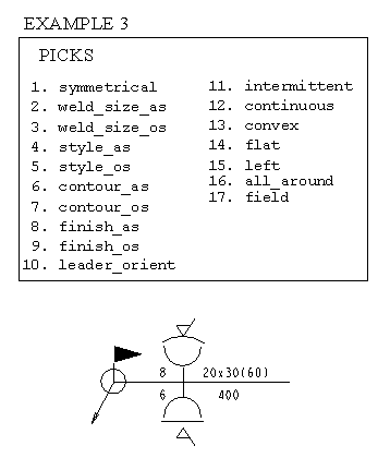
Symbol Definition Structure
Surface Joint Symbol: Surface_Joint.sym
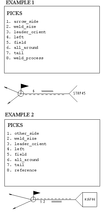
Symbol Definition Structure
Surfacing Symbol: Iso_Surfacing.sym
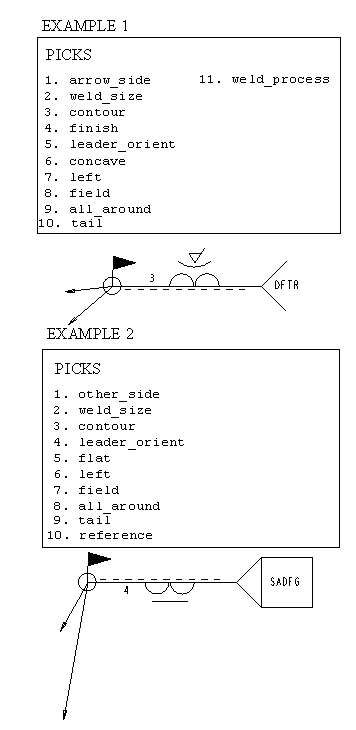
Symbol Definition Structure
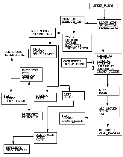
Steep-flanked V-butt Symbol: Steep_V.sym
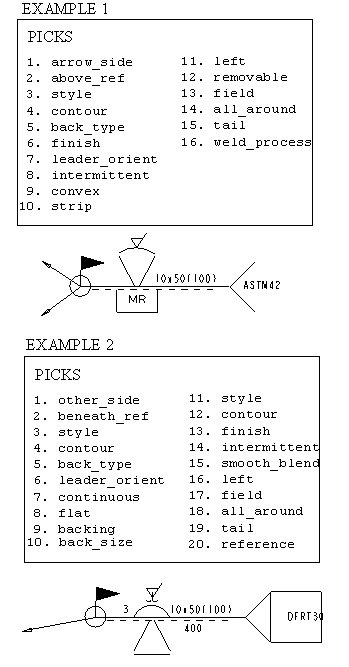
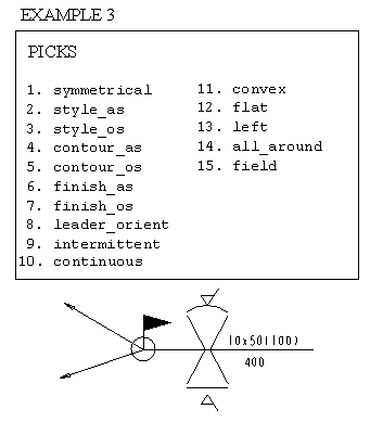
Symbol Definition Structure
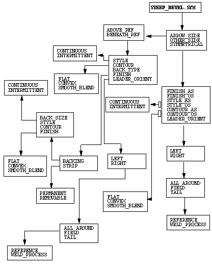
Steep-flanked Bevel Butt Symbol: Steep_Bevel.sym
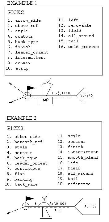
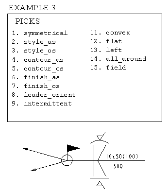
Symbol Definition Structure
V-butt with Broad Root Face Symbol: Broad_Root_V.sym
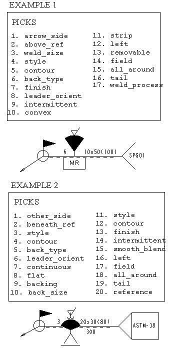
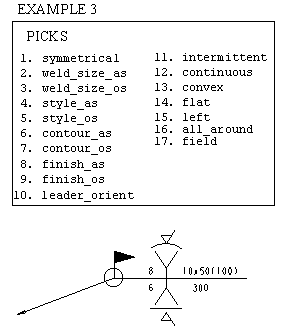
Symbol Definition Structure
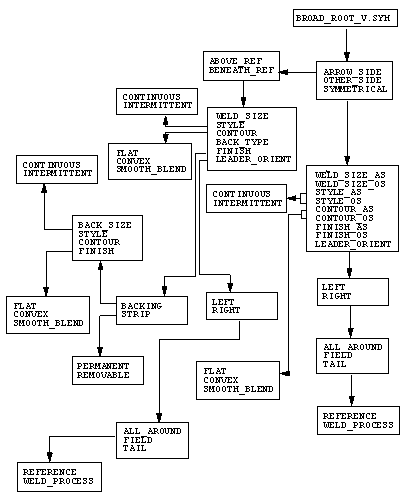
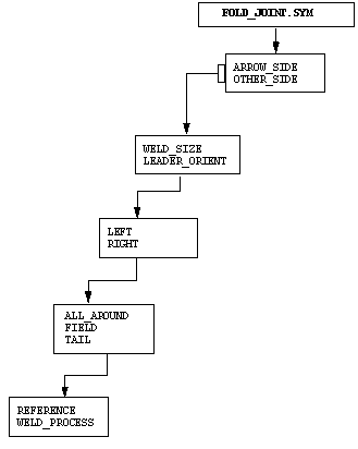
Fold Joint Symbol: Fold_Joint.sym
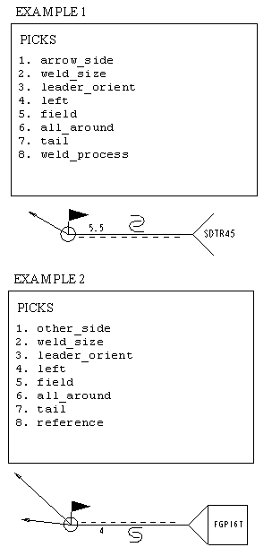
Symbol Definition Structure
Combine Symbol: Combine.sym
Symbol Definition Structure
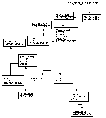
Edge Flanged Symbol: Iso_Edge_Flange.sym
Symbol Definition Structure
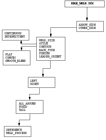
Edge Symbol: Edge_Weld.sym
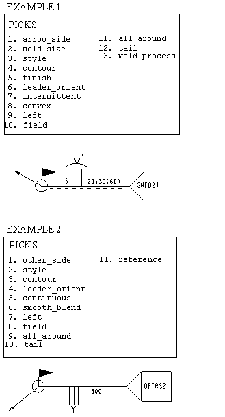
Symbol Definition Structure
