About Ordinate Dimensions
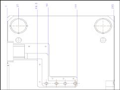
Ordinate dimensions use a single witness line with no leader, and are associated with a baseline reference, shown in the following figure as ".00". All dimensions that reference the same baseline share a common plane or edge.
You can use new or existing start points to create ordinate dimensions.
You can use a combination of following drawing options to control the format display of the ordinate dimensions:
• ord_dim_standard—Sets the standard. For example, std_jis places dimensions along a connecting line that is perpendicular to the baseline and starts with an open circle.
• draw_arrow_style—Controls the style of the arrow and circle whether they are open, closed, or filled.
• draw_dot_diameter—Sets the diameter for the leader line dots (the circle on the baseline).
The display of rounded ordinate dimensions is similar to that of rounded linear dimensions. When you select an ordinate dimension baseline, the Round Dimension check box appears grayed out in the Dimension ribbon tab, and you cannot change the state of this check box. Ordinate dimension baselines always display a zero value according to the number of decimal places defined in the Dimension ribbon tab or the settings of the lead_trail_zeros drawing option.
The Ordinate Style option on the Display panel, under the Display group of the Dimension ribbon tab is available only when you select at least a single ordinate dimension. |
While adding a new ordinate dimension to an existing ordinate dimension or ordinate dimension group, you can select the existing baseline, the entity that the baseline is attached to, or any part of an existing ordinate dimension's witness line or text as the reference.