About Using Placement Constraints
A placement constraint specifies the relative position of a pair of references. Follow these general principles for placement constraints:
• When an offset value is entered for a constraint, the system displays the offset direction. To select the opposite direction, click the yellow arrow, enter a negative value, or drag the drag handle in the graphics window.
• Constraints are added one at a time. You cannot use a single constraint to constrain two different holes in one part with two different holes in another part. You must define two separate constraints.
• Placement constraint sets are used to completely define placement and orientation. For example, you can constrain one pair of surfaces to be coincident, another pair to be parallel, and a third pair to be normal.
• A revolved surface is a surface created by revolving a section or by extruding an arc or circle. The only surfaces that may be used in a placement constraint are planes, cylinders, cones, tori, and spheres.
• The term same-surface refers to a set of surfaces that includes a seed surface and all surfaces connected through artificial edges. For example, a cylindrical surface created through Extrude or Revolve is made of two surfaces connected through two artificial edges. Cylinders, cones, spheres, and tori are surfaces that can be used as references.
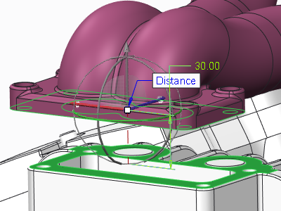
Distance Constraint
Use the Distance constraint to position the component reference at set distance from the assembly reference. To show an additional Mate or Align label for a Distance constraint, see the topic About Showing Mate and Align for the Coincident and Distance Constraints. References for a Distance constraint can be point-point, point-line, line-line, plain-plain, planar surface-planar surface, point-plane, or line-plane.
In the figure below, the bottom surface of the part is a distance of 30.00 from the selected assembly surface.
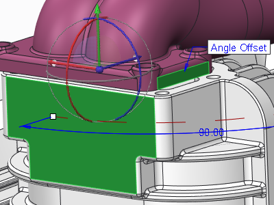
Angle Offset
Use the Angle Offset constraint to position the selected component reference at an angle to the selected assembly reference. References for an Angle constraint can be line-line (coplanar lines), line-plane, or plain-plain.
In the figure below the surface of the part being assembled is at a 90.00° angle to the selected assembly surface (green).
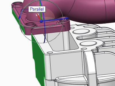
Parallel Constraint
Use the Parallel constraint to place the component reference parallel to the assembly reference. References for a Parallel constraint can be line-line, line-plane, or plain-plain.
In the figure below the surface of the part being assembled (green) parallel to the selected assembly surface (green).
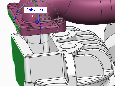
Coincident Constraint
Use the Coincident constraint to position the component reference coincident with the assembly reference. To show an additional Mate or Align label for a Coincident constraint, see the topic About Showing the Coincident and Distance Constraint Mate and Align. References for a Coincident constraint can be points, lines, planes or planar surfaces, cylinders, cones, point-on-curve, and any mix of these references.
To set the default constraint to be Coincident, set the auto_constr_always_use_offset configuration option to never.
In the figure below the side surface of the part being assembled is coincident to the side surface assembly reference.
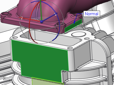
Normal Constraint
Use the Normal constraint to position the component reference normal to the assembly reference. References can be line-line (coplanar lines) line-plane, or plane-plane.
In the figure below the surface of the part being assembled (green) is normal to the selected assembly surface (green).
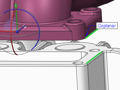
Coplanar Constraint
Use the Coplanar constraint to position a component edge, axis, intent datum axis, or surface, coplanar to a similar assembly reference. References can only be line-line.
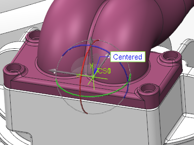
Centered Constraint
Use the Centered constraint to center pairs of conical surfaces, spherical surfaces, and toroidal surfaces. You can select a pair of surfaces, coordinate systems, or intent coordinate systems. References can be cone-cone, torus-torus, or sphere-sphere. When you select coordinate systems or intent coordinate systems as references, the coordinates system origins are aligned with three degrees of freedom.
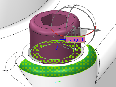
Tangent Constraint
Use the Tangent constraint to control the contact of two surfaces at their point of tangency. An example of the use of this constraint is the contact surface or point between a cam and its actuator.
Default Constraint
Use the Default constraint to align the default system-created coordinate system of the component to the default system-created coordinate system of the assembly. The system places the component at the assembly origin. References can be csys-csys, or point-csys.
Fix Constraint
Use the Fix constraint to fix the current position of a component that was moved or packaged.
Oriented Constraint
Use the Oriented constraint as the second constraint to constrain two different axes in one part, with two different axes in another part. This constraint is useful when the second axis of one part is not exactly coincident to the second axis of the other part. The following conditions must exist for the Oriented constraint to be available:
• The first pair of axes are constrained using a Coincident constraint.
• Axes in both parts are on the same plane and parallel to each other.