About L_MIN and H_MIN Dimensions in Non-Standard Beam End Copes
It is important to understand the meaning of L_MIN and H_MIN dimensions when creating beam end copes.
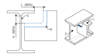
L_MIN is the minimum distance between the outside surface of the attaching beam's flange and the end of the cope (see figure above). When you create the cut for the cope, the cut length is calculated to leave the smallest distance (the minimum) to the flange. The next largest allowed cut length value is defined by the beam_end_cope_dims.cfg file located in the Creo Advanced Framework installation directory configuration subdirectory. These ensure even values (such as 100, 110, 120 mm) while retaining the user-defined L_MIN. The length updates if the flange width of the attaching beam changes. L_MIN specifies the minimum distance from the upper end of the attaching surface to the bottom of the cut. The height needed to maintain the distance is calculated, and the next largest value is selected for the cut height from the H_MIN beam_end_cope_dims.cfg file.
To obtain correct cut values, do not change the default values. Activate the beam_end_cope_dims.cfg file if you want to customize values.
The beam end cope command appears in the Element Definition dialog box for steel connections. Select or clear the check box to toggle the cope command and use the L_MIN and H_MIN dimensions.