Program Zero Usage
You can define Program Zero at the operation level or at the machining feature level:
• Operation Program Zero—Specified at the time of operation setup; acts as the default origin for the NC output. All machining features created within a certain operation will use the same operation Program Zero.
• Feature Program Zero—Specified at the time of defining a feature; defines the orientation of the stock on the machine and affects the tool path creation, such as retract and cut feed direction. The feature Program Zero coordinate system must be oriented in a certain way, as described in the following section.
If you do not explicitly define a feature Program Zero, the system will implicitly use the operation Program Zero to define the orientation of the stock on the machine and generate tool path. However, the Program Zero setting is modal, that is, once you specify a separate Program Zero for a feature, it will stay for all subsequent features until you change it.
If the operation and feature Program Zeroes are different, then, upon creating the tool path for a feature, all the cutter location (CL) data will be transformed and output in the coordinates of the operation Program Zero coordinate system. If the z-axes of the two coordinate systems are not parallel, the tool orientation vector (i,j,k) or table rotation will be provided. This functionality allows you to postprocess 3-axis operations to be performed on the 5-axis machines.
|
|
You can specify that the linear and rotational transitions between the two Program Zero coordinate systems be output in the CL file, instead of transforming all CL coordinates, by using Multiple Axis Output Options in the Machine Tool Setup dialog box.
|
Z-axis Orientation
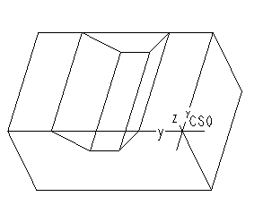
The Program Zero coordinate system at the feature level should be oriented so that the positive z-axis points away from the holding fixtures of the machine. For example, on a vertical milling machine, the positive z-axis points up, away from the table surface. The following illustration shows the z-axis orientation for milling.
