To Combine and Uncombine Welds
To Combine Welds
1. Click > . The Welding tab opens.
2. Click  Combine. The Combine Welds tab opens.
 Combine. The Combine Welds tab opens.
You can also right-click a weld that is not combined in the Model Tree and choose  Combine from the shortcut menu. Combine from the shortcut menu. |
3. Select a combined weld type:
◦ Create a reinforced combined weld.
Reinforced combined welds are comprised of one groove or butt weld plus one fillet weld. The groove or butt weld must be positioned higher in the Model Tree than the fillet weld. The groove or butt weld must be at the same hierarchical level as the fillet weld.
1. Click  reinforce.
 reinforce.
2. Click the References tab.
3. Click the Reinforcement reference collector, and then in the graphics window or Model Tree, select a fillet weld or groove or butt weld.
4. To select the second reference, press and hold CTRL, and select a fillet weld (if the first reference is a groove or butt weld) or a groove or butt weld (if the first reference is a fillet weld).
The fillet weld must be positioned lower in the Model Tree than, but at the same hierarchical level as, the groove or butt weld. |
◦ Create a both sides combined weld.
Both sides combined welds are comprised of between two and four welds located on both sides of a single welded component.
1. Click  both sides.
 both sides.
2. Click the References tab.
3. Click the Arrow Side reference collector, and in the graphics window or Model Tree, select a fillet weld or groove or butt weld.
4. To select a second weld in the Arrow Side reference collector, hold down the CTRL key and select a fillet weld (if the first reference is a groove or butt weld) or a groove or butt weld (if the first reference is a fillet weld).
5. Click the Other Side reference collector, and in the graphics window or Model Tree, select a fillet weld or groove or butt weld.
6. To select a second weld in the Other Side reference collector, hold down the CTRL key and select a fillet weld (if the first reference is a groove or butt weld) or a groove or butt weld (if the first reference is a fillet weld).
The fillet weld must be positioned lower in the Model Tree than, but at the same hierarchical level as, the groove or butt weld. |
◦ Create a similar combined weld.
Similar combined welds are comprised of welds that have exactly the same weld definition, and that differ only by references used to define location.
1. Click  similar.
 similar.
2. Click the References tab.
3. Click the Similar reference collector, and in the graphics window or Model Tree, select a weld.
4. To select additional references, hold down the CTRL key and select additional welds that have the same weld definition.
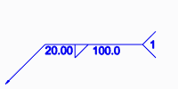
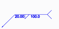
4. To show the sequence ID number in the welding symbol tail, click the Options tab, and select the Display sequence ID check box. To hide the sequence ID number, clear the check box.
When all the welding features referenced by the combined weld have the same visibility for the sequence ID, the combined weld inherits this visibility. When the visibility is not the same for all the welding features referenced by the combined weld, then the visibility is taken from the Weld Preferences dialog box. |
Show sequence ID | Hide sequence ID |
|---|---|
 |  |
5. Click the Symbol tab, and define the properties of the weld symbol displayed in the graphics window.
6. To add a user-defined parameter, click the Properties tab, and then click Define. Enter a parameter in the Parameters dialog box that opens.
7. Click  . The combined weld is displayed in the Model Tree.
 . The combined weld is displayed in the Model Tree.
To Uncombine Welds
When you uncombine a combined weld, the welds that comprise the combined weld revert to independent welds, each with its own sequence ID. You can uncombine welds that were combined using versions earlier than Creo Elements Pro 5.0.
1. Select the combined weld feature in the Model Tree.
2. Click  Uncombine, or right-click the combined weld and choose
  Delete from the shortcut menu.
 Uncombine, or right-click the combined weld and choose
  Delete from the shortcut menu.
 Welding