About Welding Geometry Types
After deciding the type of feature to create, you also decide how to represent geometry in your design. The table shows the geometry representation that you can use with each weld feature or edge preparation feature:
|
Weld or Edge Preparation Feature
|
Geometry Representation
|
|---|---|
|
Fillet, groove/butt, plug/slot welds
|
• Surface
• Light
• Solid
|
|
Spot welds
|
• Surface
• Light
|
|
Edge preparations
|
• Solid
• Light
|
Surface—Creates and shows the surface geometry within the design. The weld feature contains all the necessary data for manufacture and is represented by surface geometry in the design.
Light—References existing curves or edges but has no geometry of its own. The weld or edge prep feature contains all the necessary data for manufacture, but is represented by the geometry it references (edge, surface). The lack of solid edge preparation geometry can significantly reduce the regeneration and graphic load times for your design.
Solid—Solid welds and edge preparations are geometric models that offer mass properties such as volume and surface area.


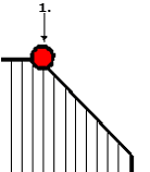
1. Reference for solid edge preparation
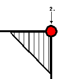
2. Reference for light edge preparation
Because light geometry maintains all the necessary edge preparation and weld parameters, you can quickly convert light to solid or surface (and vice versa) for manufacturing and design purposes. If you are creating a number of welds and edge preparations in your model, consider creating (and keeping) all the welds and edge preparations as light geometry and then converting them to surface or solid as needed for manufacturing.
• You can customize the naming conventions for edge preparation model instances. On the Welding tab, click  Preferences. The Weld Preferences dialog box opens. Select General from the list, and click the Family Table tab. Select the Create Family Table Instance check box, and type a name format in the New instance name format box. During startup only, the weld_edge_prep_name_suffix configuration option provides naming conventions. Preferences. The Weld Preferences dialog box opens. Select General from the list, and click the Family Table tab. Select the Create Family Table Instance check box, and type a name format in the New instance name format box. During startup only, the weld_edge_prep_name_suffix configuration option provides naming conventions.• You can specify if the edge preparation feature will be visible in the generic model or only in the single instance. On the Welding tab, click  Preferences. The Weld Preferences dialog box opens. Select General from the list, and click the Family Table tab. Select the Create Family Table Instance check box. Under Create edge preparation and weld features, select In generic model to create a feature in the generic model, or select In instance model only to create a feature in the single model instance. During startup only, the weld_edge_prep_instance configuration option sets where edge preparation features are visible. Preferences. The Weld Preferences dialog box opens. Select General from the list, and click the Family Table tab. Select the Create Family Table Instance check box. Under Create edge preparation and weld features, select In generic model to create a feature in the generic model, or select In instance model only to create a feature in the single model instance. During startup only, the weld_edge_prep_instance configuration option sets where edge preparation features are visible.• When using light edge preparations, be sure to note the information for the welding mass properties calculation ( > ). The mass for light edge preparation is not calculated automatically. Therefore, without user action, the light edge mass is not considered in mass calculations. |
 Mass
Mass