Tutorial 5: Creating a New Part by Copying Geometry of a Body
In this tutorial you create a new part from a body. You then update the original part and see how this affects the new part.
|
|
• It is recommended that you work through the exercises sequentially during one Creo Parametric session.
• In the exercises that follow you are instructed to use commands from the ribbon. After selecting items, you can also access these commands from the mini toolbar or by right-clicking. • In the videos of the exercises, to exit a tool a middle-click was used instead of  in many instances. in many instances. |
This tutorial is divided into 5 exercises to make it easier to follow:
• Exercise 1: Resume Suppressed Features—Drag the indicator in the Model Tree to roll the model forward.
• Exercise 2: Split the Body into 2 Bodies—Split out a disjoint volume as a new body.
• Exercise 3: Create a New Part from Body PIECE1—Create a new part from a body and set update control options.
• Exercise 4: Create a New Part from Body PIECE2—Create a new part from a body and set update control options.
• Exercise 5: Create Rounds—Create rounds on the master part and see how they are propagated to the clamp parts.
Exercise 1: Resume Suppressed Features
Watch a video that demonstrates the steps in this exercise and the next exercise:
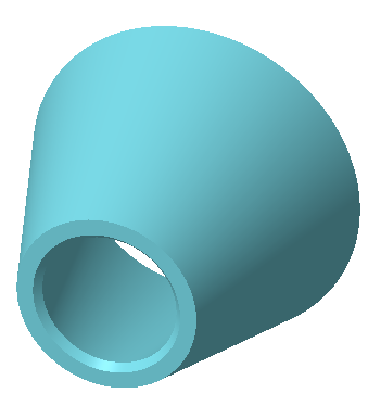
1. Set the working directory to tutorial5. and open clamp_master.prt.
2. Click  and clear the (Select All) check box to turn off datum display in the graphics window.
and clear the (Select All) check box to turn off datum display in the graphics window.3. In the Model Tree, drag the green indicator below the last 2 features.
This concludes the first of 5 exercises.
Exercise 2: Split the Body into 2 Bodies
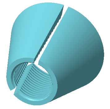
1. Expand the Bodies folder in the Model Tree and select PIECE1.
2. Click  Split Body. The Split Body tab opens.
Split Body. The Split Body tab opens.3. Click  Volume.
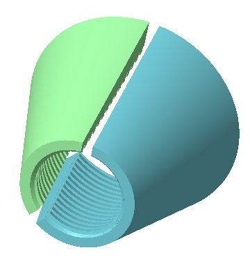
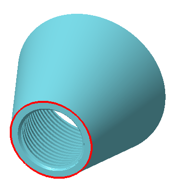
Volume.4. Select a surface that belongs to one volume as you see in the following picture.
5. Click .
.
6. Click the new body twice, type the name piece2, and press ENTER.
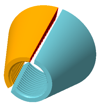
7. Select body PIECE2.
8. Click View.
9. Click the arrow below  Appearances and click the green circle as you see in the following picture.
Appearances and click the green circle as you see in the following picture.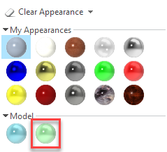
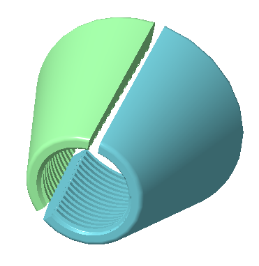
10. The appearance of PIECE2 changes to green.
11. Click Model to return to the Model tab.
12. Select body PIECE2, right-click, and select Parameters. The Parameters dialog box opens.
13. Click  . A new parameter is added to the list of parameters.
. A new parameter is added to the list of parameters.14. Name the parameter piece_num.
15. Click in the Type box and change the type to Integer.
16. Click in the Value box and type 2.
17. Click OK.
This concludes the second of 5 exercises.
Exercise 3: Create a New Part from Body PIECE1
In this exercise a new part is created as a Copy Geometry feature of a body. Parameters and properties of the original body are copied with the part. After creating the part, you set update control options to determine how or if the part is updated when the original body changes.
Watch a video that demonstrates the steps in this exercise:
1. In the Model Tree select PIECE1, right-click, and select Create Part from Body. The New Part from Body dialog box opens.
2. Type a new file name, clamp_p1.
3. Click OK. The new part, CLAMP_P1, opens in the graphics window. Note that the only feature in the Model Tree is an extern Copy Geom feature.
4. Expand the Bodies folder. Note that the body name is PIECE1.
5. Select body PIECE1, right-click, and select Parameters. The Parameters dialog box opens. Note that the parameter PIECE_NUM has the value 1.
6. Click OK.
7. Right-click the extern Copy Geom feature, and select  . The Copy Geometry tab opens.
. The Copy Geometry tab opens.8. Click Options.
9. Select Manual Update and select the Provide Notification check box.
10. Click .
.This concludes the third of 5 exercises.
Exercise 4: Create a New Part from Body PIECE2
Watch a video that demonstrates the steps in this exercise:
1. Return to the CLAMP_MASTER part window.
Click the arrow next to  on the Quick Access Toolbar to select a different window. on the Quick Access Toolbar to select a different window. |
2. Select PIECE2, right-click and select Create Part from Body. The New Part from Body dialog box opens.
3. Type a new file name, clamp_p2.
4. Click OK. The new part, CLAMP_P2, opens in the graphics window. Note that the only feature in the Model Tree is an extern Copy Geom feature.
5. Expand the Bodies folder. Note that the body name is PIECE2.
6. Select body PIECE2, right-click, and select Parameters. The Parameters dialog box opens. Note that the parameter PIECE_NUM has the value 2.
7. Click OK.
8. Right-click the extern Copy Geom feature, and select Update Control note that Automatic Update is selected.
This concludes the fourth of 5 exercises.
Exercise 5: Create Rounds
Watch a video that demonstrates the steps in this exercise:
1. Return to the CLAMP_MASTER part window.
2. Drag the green indicator at the bottom of the Model Tree above Extrude 1.
3. Select the bottom edge of the part and click Round. The Round tab opens.
4. Select the top edge of the part and set the round radius to 1.00.
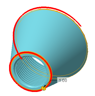
5. Click .
.
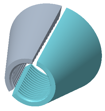
6. Drag the green indicator to the bottom of the Model Tree. The part with 2 bodies updates and the rounds are added.
7. Return to CLAMP_P1 part. Note that the extern Copy Geom feature has a yellow triangle, the sign of an out of date feature. This part was set to manual update with notification.
8. Select the feature in the Model Tree, right-click, and select >  Update. The rounds appear on the updated part.
Update. The rounds appear on the updated part.
9. Return to CLAMP_P2 part.
10. Click  on the Quick Access toolbar or
  below the graphics window. The part regenerates and the rounds appear. This part was set to automatic update.
on the Quick Access toolbar or below the graphics window. The part regenerates and the rounds appear. This part was set to automatic update.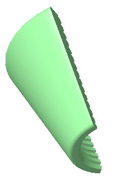
This concludes tutorial 5.