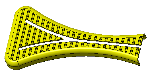
Tutorial 2: Creating Complex Grooves in a Plastic Handle Using Patterned Geometry of a Body
In this tutorial, you learn how to use a body as a design tool to remove material from a part.
• It is recommended that you work through the exercises sequentially during one Creo Parametric session. • In the exercises that follow you are instructed to use commands from the ribbon. After selecting items, you can also access these commands from the mini toolbar or by right-clicking. • In the videos of the exercises, to exit a tool a middle-click was used instead of  in many instances. in many instances. |
This tutorial is divided into 4 exercises to make it easier to follow:
• Exercise 1: Create the Tool Body—Create a body to use as a tool for removing material.
• Exercise 2: Pattern the Extrude with the Chamfers—Pattern the tool body.
• Exercise 3: Remove Unnecessary Material—Remove excess material from the tool body so it follows the shape of the original body.
• Exercise 4: Create a Boolean Subtract Feature—Subtract the material of the patterned tool body to create the cutout pattern you wanted on the original body.
Exercise 1: Create the Tool Body
Watch a video that demonstrates the steps in this exercise:
1. Set the working directory to tutorial2 and open tool_body_demo.prt.
2. Click  and clear the (Select All) check box to turn off datum display in the graphics window.
and clear the (Select All) check box to turn off datum display in the graphics window.3. Select the Front datum plane in the Model Tree and click  Extrude.
Extrude.4. Click  to orient the sketching plane parallel to the screen. Click
  and click and drag a square around the upper-right corner of the part.
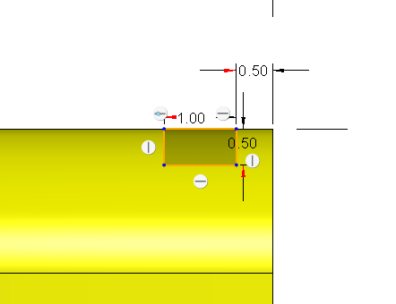
to orient the sketching plane parallel to the screen. Click and click and drag a square around the upper-right corner of the part.5. Sketch a rectangle on the upper-right surface of the part.
6. Set the dimensions as you see in the following picture. Dimension the rectangle, 1.00 x 0.50. Create a distance dimension of 0.50 from the end of the part.
7. Click .
.8. Set the extrude Depth to  Symmetric with a value of 45.
Symmetric with a value of 45.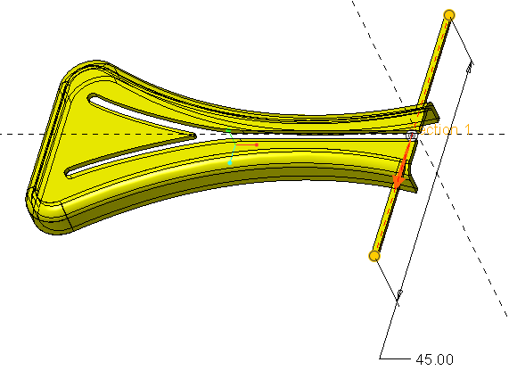
9. In the ribbon, click Body Options, or right-click in the graphics window, and then select the Create new body check box.
Unless you specify a different body or create a new body, geometry is created in the default body. |
10. Click . A new body (Body 2) is added as the default body to the Model Tree Bodies folder.
. A new body (Body 2) is added as the default body to the Model Tree Bodies folder.11. Select the bottom edge of the extrude as you see in the following picture. Click  Chamfer. The Chamfer tab opens.
Chamfer. The Chamfer tab opens.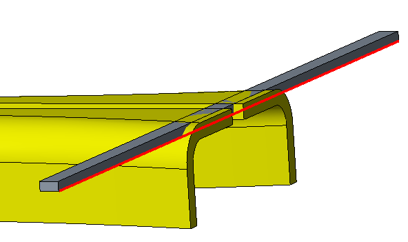
12. Set the chamfer dimension to 0.3 and select the opposite edge of the extrude.
13. Click . A chamfer is created on both edges.
. A chamfer is created on both edges.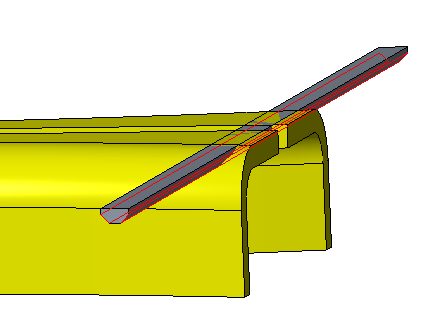
This concludes the first of 4 exercises.
Exercise 2: Pattern the Extrude with the Chamfers
Watch a video that demonstrates the steps in this exercise:
1. Select the extrude and the chamfer in the Model Tree and click  to create a group.
to create a group.2. With the newly created group selected, click  Pattern.
Pattern.3. Make sure the pattern type is Dimension. You are creating a pattern in one dimension.
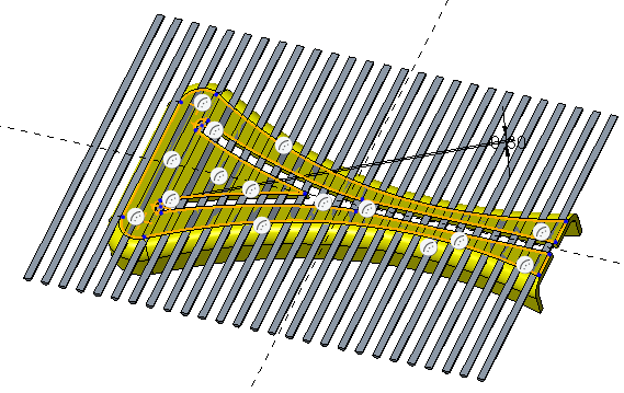
4. Select the 0.5 dimension from the edge and type 2.5. This is the distance between the pattern members. Click Dimensions to view the chosen dimension and the value.
5. Type 27 in the Number of members box.
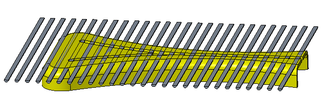
6. Click .
.This concludes the second of 4 exercises.
Exercise 3: Remove Unnecessary Material
Watch a video that demonstrates the steps in this exercise and the next exercise:
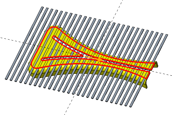
1. Select the top surface of the first extrude in Body 1.
2. Click Extrude. The Sketch tab opens.
Extrude. The Sketch tab opens.3. Click  Offset and select Loop in the Type dialog box.
Offset and select Loop in the Type dialog box.4. Select the surface again and type -0.3 as the offset value dimension.
5. Click  or press ENTER.
or press ENTER.6. Close the Type dialog box.
7. Click .
.8. In the Extrude tab, select  Remove Material.
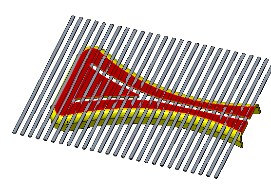
Remove Material.9. Set the depth to 5.0 and make sure both arrows are pointing as shown in the following picture.
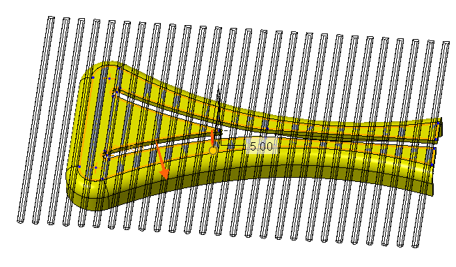
You can click the arrow to change the direction of the extrude. |
10. Click . The unnecessary material is removed from Body 2.
. The unnecessary material is removed from Body 2.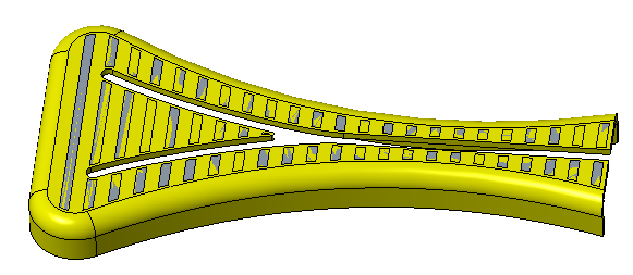
This concludes the third of 4 exercises.
Exercise 4: Create a Boolean Subtract Feature
1. Click  Boolean Operations.
Boolean Operations.2. Click  Subtract.
Subtract.3. Select Body 1 as the Body to modify.
4. Select Body 2 as the Modifying body.
5. Click . The geometry of Body 2 is removed from Body 1.
. The geometry of Body 2 is removed from Body 1.This concludes tutorial 2.