Creating Sketches
1. On the Model tab, click  Sketch from the Datum group. The Sketch dialog box opens.
Sketch from the Datum group. The Sketch dialog box opens.2. In the Sketch dialog box, do the following:
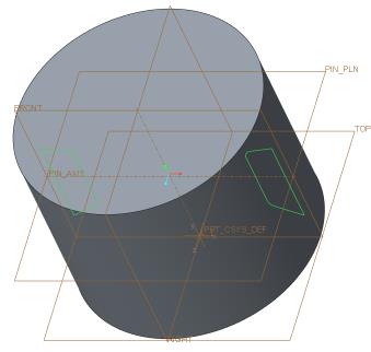
a. Select the datum plane FRONT as the sketching plane.
b. Click in the Reference box and select the datum plane TOP.
c. Select Top from the Orientation list.
d. Click Sketch. The Sketch tab opens.
3. Right-click in the graphics window and click References. The References dialog box opens.
4. Select the datum plane PIN_PLN and click Close.
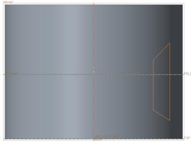
5. Click  Sketch View on the in-graphics toolbar.
Sketch View on the in-graphics toolbar.6. Click  Line from the Sketching group.
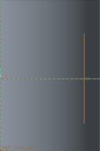
Line from the Sketching group.a. Sketch the first line parallel to right edge. The letter V appears when the line is vertical.
b. Sketch the first angled line.
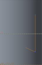
c. Sketch the second vertical line parallel to the first line.
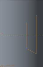
d. Close the shape by connecting the second vertical line to the starting point of the first line.
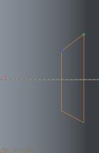
7. Middle-click to exit the line tool and middle-click again to exit the sketch tool.
8. Click  Centerline from the Sketching group.
Centerline from the Sketching group.a. Click anywhere on the vertical dashed line.
b. Move the pointer. The centerline is attached to the pointer.
c. Click the vertical dashed line again to define the centerline placement.
9. Click  Dimension from the Dimension group. The dimensions for the sketch appear in the graphics window.
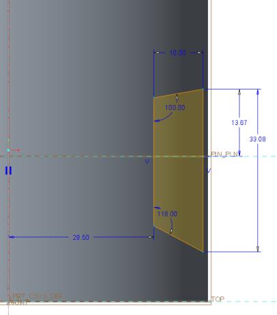
Dimension from the Dimension group. The dimensions for the sketch appear in the graphics window.10. In the graphics window, do the following:
a. Click the left vertical line and the top angled line. Middle-click to define the angle value. Edit the value to 100 and press ENTER.
b. Click the left vertical line and the bottom angled line. Middle-click to define the angle value. Edit the value to 118 and press ENTER.
c. Click the datum plane PIN_PLN and the intersection point of the vertical line and top angled line. Middle-click to define the height from the datum plane. Edit the value to 13.67 and press ENTER.
d. Click the left vertical line and the right vertical line. Middle-click to define the width. Edit the value to 10 and press ENTER.
e. Double-click the remaining dimensions and edit the values as shown in the following figure.
11. Click  Fillet from the Sketching group.
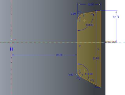
Fillet from the Sketching group.12. In the graphics window, do the following:
a. To create the top fillet, select the left vertical line and the top angled line.
b. To create the bottom fillet, select the left vertical line and the bottom angled line.
c. Middle-click to exit the fillet tool.
d. Double-click the remaining dimensions and edit the values as shown in the following figure.
13. Click  Select from the Operations group.
Select from the Operations group.14. Hold the left mouse button and drag a box around the sketch that you have created.
15. Click  Mirror from the Editing group and click the vertical centerline. The sketch is mirrored across the vertical centerline.
Mirror from the Editing group and click the vertical centerline. The sketch is mirrored across the vertical centerline.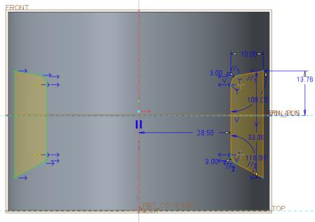
16. Right-click in the graphics window and click  Save the sketch and exit.
Save the sketch and exit.17. On the in-graphics toolbar, click  Saved Orientations and then click Default Orientation.
Saved Orientations and then click Default Orientation.