Vortex Shedding: Exercise 2—Preparing the Mesh
A mesh is a computational grid inside, outside, or both inside and outside any closed geometry defined by a CAD surface.
Generating the Mesh
1. In the Flow Analysis Tree, select Domains.
2. In the Properties panel, Model tab, for Mesh Generation, type the following values:
◦ Cell Size Specification—Absolute
◦ Maximum Cell Size — 0.1
◦ Minimum Cell Size — 0.001
◦ Cell Size on Surfaces — 0.05
3. Create two refinement zones, type the following values:
◦ Refine Zone Options—Box Zone
◦ Cell Size—0.025
◦ First Corner— -1, -1.5, 0
◦ Diagonal Corner— 10, 1.5, 0.05
4. Click  Generate Mesh to create the mesh for the fluid domain. If the Info dialog box opens, click Yes to convert all the units.
Generate Mesh to create the mesh for the fluid domain. If the Info dialog box opens, click Yes to convert all the units.Viewing the Mesh
1. Click  in the Graphics toolbar to display the style elements. Select
  No Hidden,
  Hidden Line, or
  Wireframe to display the mesh.
in the Graphics toolbar to display the style elements. Select No Hidden, Hidden Line, or Wireframe to display the mesh.2. Clear  CAD Bodies and
  Flow Analysis Bodies.
CAD Bodies and Flow Analysis Bodies.3. Select Domains.
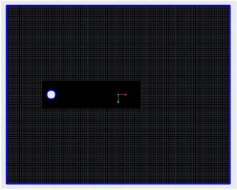
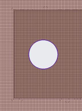
4. In the Properties panel, View tab, set Keep drawing, Grid, and Outline to Yes. The mesh for the boundary VORTEX_SHEDDING appears in the graphics window.