Multicomponent Mixing using a Nozzle: Exercise 1—Extracting the Fluid Domain
Fluid domain extraction is the creation of a closed geometric region that surrounds the fluid.
1. Click > and navigate to the Advanced_FlowAnalysisModels folder. Click OK.
2. Click >  Open.
Open.
Open.3. From the File Open dialog box, browse to the Multi-component-mixing folder and select MIXING_NOZZLE.asm. Click Open.
4. Click  in the Graphics toolbar to display the style elements. Select Shading, or
  Shading with Edges.
in the Graphics toolbar to display the style elements. Select Shading, or Shading with Edges.5. Click the Applications tab.
6. Click  Flow Analysis. The Flow Analysis tab opens.
Flow Analysis. The Flow Analysis tab opens.7. Click  New Project. If the Residual plot opens, close it.
New Project. If the Residual plot opens, close it.8. Click  Create Fluid Domain. The Fluid Domain Creation tab opens.
Create Fluid Domain. The Fluid Domain Creation tab opens.9. Click the Openings tab.
10. Click the Faces box. The Surface Sets dialog box opens.
11. In the Surface Sets dialog box, under Included surfaces right-click all the surfaces and click Remove All.
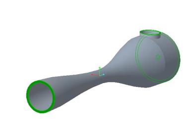
12. In the graphics window, press CTRL and select the four surfaces shown below. Four surfaces appear in the Surface Sets dialog box, under Included surfaces.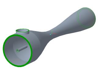
13. Click OK.
14. In the Fluid Domain Creation tab click  to create the fluid domain.
to create the fluid domain.Splitting the Boundary
1. In the Model Tree, right-click MIXING_NOZZLE_1_FLUID.PRT.
2. Click  . The part opens in a new window. Make this the active window.
. The part opens in a new window. Make this the active window.3. In the MIXING_NOZZLE_1_FLUID.PRT window, click the Editing list.
4. Click  Split Surface.
Split Surface.5. In the Split Surface tab, click Placement.
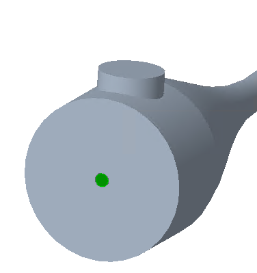
6. Select the nozzle opening as shown below.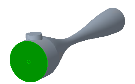
7. Click the Selected contours box and select the fuel pipe opening as shown below.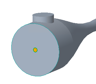
8. Click .
.9. In the Operations group, click  Regenerate. Toggle to the assembly in the window.
Regenerate. Toggle to the assembly in the window.Adding the Simulation Domain
1. In the Simulation Domains group, click  Select Simulation Domains.
Select Simulation Domains.2. Click Add fluid domain.
3. In the Model Tree, select MIXING_NOZZLE_1_FLUID.PRT and click OK.
4. MIXING_NOZZLE_1_FLUID.PRT appears in the Model Tree. Boundaries for the boundary conditions BC_00001, BC_00002, BC_00003, and MIXING_NOZZLE_1_FLUID are created automatically. They appear in the Flow Analysis Tree under  Boundary Conditions >
  General Boundaries
Boundary Conditions > General BoundariesAdding and Renaming Boundaries
1. Under Domains, select MIXING_NOZZLE_1_FLUID.
2. In the Operations group, click Add Boundary Condition. The Surface Sets dialog box opens.
Add Boundary Condition. The Surface Sets dialog box opens.3. In the graphics window, select the fuelpipe opening shown below.
4. In the Surface Sets dialog box, click OK. BC_00004 appears under General Boundaries in the Flow Analysis Tree
5. Click OK.
6. In the Flow Analysis Tree under Boundary Conditions > General Boundaries, right-click BC_00001 and select  Rename.
Boundary Conditions > General Boundaries, right-click BC_00001 and select Rename.7. In the New name box, type Nozzle_Outlet and click .
.8. In the Flow Analysis Tree under Boundary Conditions > General Boundaries, right-click BC_00002 and select Rename.
Boundary Conditions > General Boundaries, right-click BC_00002 and select Rename.9. In the New name box, type Nozzle_Side_Inlet and click .
.10. In the Flow Analysis Tree under Boundary Conditions > General Boundaries, right-click BC_00003 and select Rename.
Boundary Conditions > General Boundaries, right-click BC_00003 and select Rename.11. In the New name box, type Nozzle_Inlet and click .
.12. In the Flow Analysis Tree under Boundary Conditions > General Boundaries, right-click BC_00004 and select Rename.
Boundary Conditions > General Boundaries, right-click BC_00004 and select Rename.13. In the New name box, type Fuelpipe_Inlet and click .
.