Mixing Tank: Exercise 1—Extracting the Fluid Domain
Fluid domain extraction is the creation of a closed geometric region that surrounds the fluid.
1. Click > and navigate to the Advanced_FlowAnalysisModels folder. Click OK.
2. Click >  Open.
Open.
Open.3. From the File Open dialog box, browse to the Mixing_Tank folder and select mixing_tank.asm. Click Open.
4. Click  in the Graphics toolbar to display the style elements. Select Shading, or
  Shading with Edges.
in the Graphics toolbar to display the style elements. Select Shading, or Shading with Edges.5. Click the Applications tab.
6. Click  Flow Analysis. The Flow Analysis tab opens.
Flow Analysis. The Flow Analysis tab opens.7. Click  New Project. If the Residual plot opens, close it.
New Project. If the Residual plot opens, close it.8. Click  Create Fluid Domain. The Fluid Domain Creation tab opens.
Create Fluid Domain. The Fluid Domain Creation tab opens.9. Click the Seed surfaces tab.
10. Click the Faces box. The Surface Sets dialog box opens.
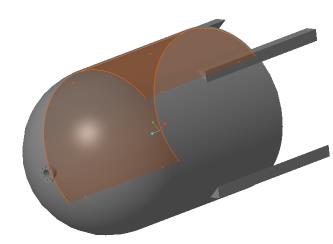
11. Right-click to select the interior surface shown below as the seed surface on the display panel. The surface appears in the Surface Sets dialog box, under Included surfaces.
12. Click OK. MIXING_TANK_1_FLUID.prt appears in the Model Tree.
Splitting the Simulation Domain
1. Select MIXING_TANK_1_FLUID.prt in the Model Tree.
2. Click Split Domain. The Split Tool tab opens.
3. Set Split type to Cylinder.
4. Set Axis to Z.
5. Set Center point to 0,0,0.
6. Set Radius to 0.38.
7. Click  to create the cylindrical split.
to create the cylindrical split.8. For Enter a Split Part Name, retain the default 1 and click . Retain the default 2 and click . MIXING_TANK_1_FLUID_1.prt and MIXING_TANK_1_FLUID_2.prt appear in the Model Tree.
. Retain the default 2 and click . MIXING_TANK_1_FLUID_1.prt and MIXING_TANK_1_FLUID_2.prt appear in the Model Tree.9. Right-click MIXING_TANK_1_FLUID_1.prt and select  Rename.
Rename.10. In the New name box, type FLUID_ROTOR.prt.
11. Right-click MIXING_TANK_1_FLUID_2.prt and select Rename.
Rename.12. In the New name box, type FLUID_STATOR.prt and click OK.