Mixing Tank: Exercise 2—Adding the Simulation Domain and Boundary Conditions
1. Click  Select Simulation Domains. The Domain Model Selection box opens.
Select Simulation Domains. The Domain Model Selection box opens.2. In the Domain Model Selection box, select Add fluid domain.
3. In the Model Tree select FLUID_STATOR.prt and FLUID_ROTOR.prt.
4. Middle-click to confirm. The fluid domains appear in the Domain Model Selection dialog box under Fluid Components and in the Flow Analysis Tree under Domains.
Creating Boundary Conditions
1. Under Domains, right-click FLUID_ROTOR and select  Add Boundary Condition. The Surface Sets dialog box opens.
Add Boundary Condition. The Surface Sets dialog box opens.2. Select StationaryWall_1 as shown in the figure below.
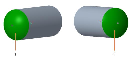
◦ 1 = STATIONARYWALL_1
◦ 2 = STATIONARYWALL_2
3. Click OK. Under General Boundaries a new entity BC_00001 is created.
4. Under Domains, right-click FLUID_ROTOR and select Add Boundary Condition. The Surface Sets dialog box opens.
Add Boundary Condition. The Surface Sets dialog box opens.5. Select StationaryWall_2 as shown in the figure.
6. Click OK. Under General Boundaries a new entity BC_00002 is created.
7. Right-click and rename the following boundary conditions:
◦ BC_00001 as STATIONARYWALL_1
◦ BC_00002 as STATIONARYWALL_2