Modifying an Endplate Connector
1. Click Framework and then in Components group click >  Modify Component. The Select dialog box opens.
Modify Component. The Select dialog box opens.2. Select the endplate as the component to modify.
3. As the endplate is assembled multiple times as identical model, the Modify Options dialog box opens. Make sure that Modify all elements is checked to modify all instances. Click OK. The Element Definition dialog opens.
4. In the W box enter 120.
5. Select the check box Holes to activate a hole pattern in the plate.
6. To define height and width of hole pattern in the H1 box enter 200 and in the W1 box enter 80.
7. Click Preview to see a preview of the modified endplate. If required modify other dimensions or options.
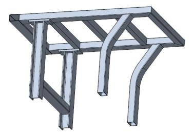
8. Click OK. All instances of the endplate are modified. Your model should look like the model shown below: