Assembling an Equipment Plate
1. Click >  New Equipment Element. The Select from Library dialog box opens.
New Equipment Element. The Select from Library dialog box opens.2. Click PLATES MM and then select PLATE. The New Component dialog box opens.
3. Click Next. The Element Definition dialog box opens.
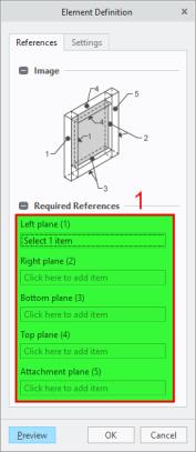
4. Define the references for plate placement. When the dialog box opens the References tab and its first reference collector is active so you can immediately start to select references. Make your selections in the order of the callouts as described below and as you can see in the picture below:
a. Left plane (1)—Select the left side surface of the left rectangular tube. b. Right plane (2)—Select the right side surface of the right square tube. c. Bottom plane (3)—Select the front surface of the front rectangular tube. d. Top plane (4)—Select the back surface of the back rectangular tube. e. Attachment plane (5)—Select the upper surface of the front rectangular tube. | 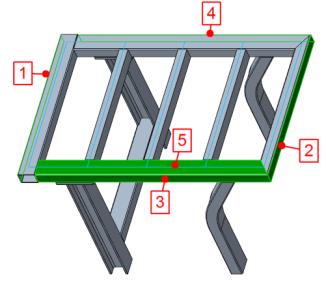 |
5. Toggle to the Settings tab of the Element Definition dialog box to define the dimensions and options for the plate.
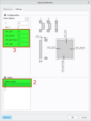
6. In the Attach option table, select A.
7. Under Enter Values, enter the offset value 10 for OFF_LEFT, OFF_RIGHT, OFF_BOTTOM, and OFF_TOP to create the plate with a 10 mm offset at each side.
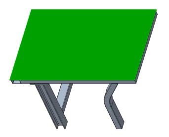
8. Click Preview to see a preview of the assembled plate. If required repeat steps 4 to 7 to select different references or enter different dimensions or options.
9. Click OK to assemble the plate.
10. Click Close to close the New Component dialog box.