Assembling a New Endplate Connector
1. Click >  New Connector Element. The Select from Library dialog box opens.
New Connector Element. The Select from Library dialog box opens.2. Click > and then select END PLATE. The New Component dialog box opens.
3. Click Next.
4. The Element Definition dialog box opens. From this dialog box, you can configure the connector element and select references required for placement.

5. First, define references for placing connector element. When the dialog box opens the References tab and its first reference collector is active so you can immediately start to select references.
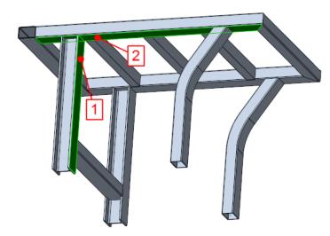
a. Referring to callout 1 in the next picture, select the I-beam surface highlighted near the upper profile end.
b. The second reference collector becomes active. Referring to callout 2, select the highlighted lower surface of the rectangular tube.
6. Toggle to the Settings tab of the Element Definition dialog box to define the size value of the endplate.
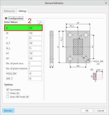
a. In the H box enter 250.
7. Click Preview to see a preview of the assembled endplate. If required repeat steps 5 and 6 to select different references or enter different dimensions.
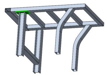
8. Click OK. The endplate is assembled and the vertical I-beam is shortened as shown in the picture below.
9. Click Close to close the New Component dialog box.