Slip Symmetry—Creo Simulation Live
A slip symmetry boundary condition can be applied to surfaces, sets of surfaces or an entire part or body in a fluid simulation study. When slip symmetry is applied to a wall, the fluid flows along the wall without friction, instead of stopping at the wall.
To Define a Slip Symmetry Boundary Condition
1. Click  Slip Symmetry. The Slip Symmetry dialog box opens.
Slip Symmetry. The Slip Symmetry dialog box opens.2. Select the surfaces to which you want to apply slip symmetry. The selected surfaces are displayed in the Surfaces collector.
Right-click and select Delete or Delete All to remove one or more surfaces from the Surfaces collector.
3. Click OK to create a slip symmetry boundary condition.
Example: Slip Symmetry Boundary Condition
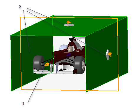
The following example shows a racing car in a wind tunnel. The input velocity is -30 m/sec along the -Z- axis. If slip symmetry is not applied to the two parallel walls and the top wall of the enclosure, the flow velocity is 0 at the walls as shown in the figure. The blue line indicates a value of zero velocity as the solver treats the walls of the enclosure as solid geometry.

1. Inlet Flow Velocity is –30 m/sec along z- axis
2. Velocity =0 at the walls with no slip symmetry applied to walls.
In this example the extents of the wind tunnel in X-and Y- direction have been reduced for demonstration purposes. In practice, the recommended cross section would be a few times larger than the object being studied. |
For the same example, you can apply slip symmetry along the two parallel side walls and the top wall of the enclosure to cause the fluid to flow along the boundary walls.
1. Inlet velocity is -30m/sec
2. Slip symmetry applied to the two parallel side walls and the top wall of the enclosure
In this case the flow velocity at the boundary walls is not zero.
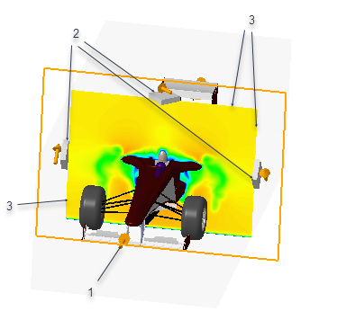
1. Inlet Flow Velocity is -30 m/sec along z- axis
2. Slip symmetry applied to the two parallel side walls and the top wall of the enclosure
3. Flow velocity at the wall boundaries is not zero