Calculating Stresses and Strains
Calculating stresses and strains can take a great deal of time. The resulting files can also be quite large, depending on the size of your model. If you do not select this check box, Creo Simulate does not provide an output or compute stresses and strains (for measures and full results) for the shells that are assigned this property.
If you want Creo Simulate to calculate these values for measures, select the Calculate Stresses and Strains check box on the Shell Property Definition dialog box. The dialog box expands to display an area for the shell "Top" location and the shell "Bottom" location. Creo Simulate uses the values that you type in these areas to calculate the stresses and strains for the corresponding areas for results. Type values for the following items:
• CZ—The distance from the midsurface of the shell at which Creo Simulate calculates stresses and strains. The software defines CZ relative to material direction 3 of the material orientation assigned to the shell, as shown below:
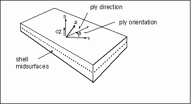
• Ply Orientation (Degrees)—The orientation of the ply material relative to the material orientation that Creo Simulate assigns to the element. The software measures the ply orientation angle,  (theta), as a counter-clockwise rotation from material direction 1 about material direction 3. The value of this item must be from –360
 to +360.
(theta), as a counter-clockwise rotation from material direction 1 about material direction 3. The value of this item must be from –360 to +360.• Material—The material at the CZ location. When you click the More button, the Materials dialog box appears.
After you select a material, Creo Simulate displays the material name.
Return to Laminate Stiffness.