Example: Rigid Link
This example illustrates a rigid link and a mesh created with and without projection.
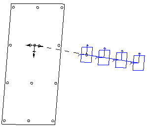
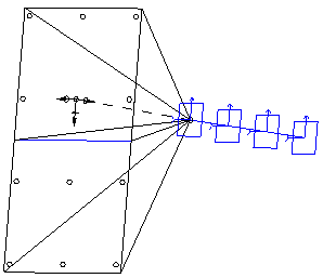
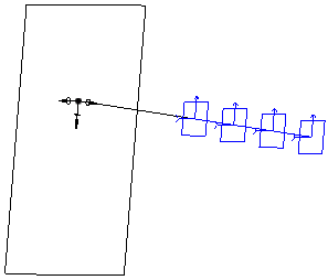
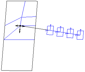
The following figures illustrate how a rigid link is displayed, both when you select and do not select the Project to References option in the Rigid Link Definition dialog box. The figures show two versions of the rigid link—the first, with no projection and the mesh created with no projection, and the second, with projection and the mesh created with projection.
The following figure represents a rigid link with no projection. The rigid link created between the selected references is displayed as a hashed line.

The following figure represents the mesh created for a rigid link with no projection. The rigid link is displayed from the selected point to the number of distribution points on the surface.

The following figure represents the rigid link created with projection. The rigid link created between the selected references is displayed as a continuous line.

The following figure represents the mesh created for a rigid link with projection. The rigid link is displayed from the selected point to the single distribution point on the selected surface.

Return to Creating Rigid Links (FEM Mode)