Best Practice: Using Fasteners in Creo Simulate
Overview
Fasteners are used to connect two components in an assembly.
The Creo Simulate fastener tool creates an idealization of a fastener. The fastener is primarily used to give a representation of the load transfer through a structure, as opposed to a bonded interface or rigid links linking surfaces together. For Creo Simulate version 2.0 and higher, default fasteners are modelled using a Timoshenko beam idealization that uses a 12x12 stiffness matrix to provide better accuracy. This type of modelling takes into account the axial forces as well as shear, torsional and bending stiffness in the fastener. There are a number of automatically created measures that describe different quantities that are calculated for a fastener during analysis.
When modeling fasteners you must remember that there is really no contact between the fastener shaft and the hole. You can model both screw or bolt fasteners. Fasteners can be modeled for solid or shell models. There are certain prerequisites for a model when using fasteners. If a fastener does not meet these prerequisites you may not be able to use the fastener or you may get error or warning messages during fastener creation or when you run an analysis.
This document expands on a few concepts that help to understand how best to use fasteners in Creo Simulate.
You can refer to the related links at the end of this document for a more detailed description of the functionality.
Creating Fasteners using Diameter and Material
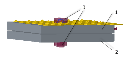
A cross section of a bolt fastener between two solid components is shown in the following figure:
1. top component
2. bottom component
3. generated annular regions kept in contact with the “Fix Separation” mechanism
4. fastener shaft diameter
5. fastener head and nut diameter
6. separation test diameter
Fig 1
You need to keep in mind certain rules when specifying the following quantities:
1. Diameter—This value is the diameter of the smallest hole in the fastener, by default. Do not specify a value greater than the diameter of the smallest hole.
2. Fastener Head and Nut Diameter—This is the value of the diameter of the bolt head and for a bolt type fastener it is the same as the nut diameter as well. Specify a value greater than the value of diameter.
3. Separation Test Diameter—This is the diameter of the annular regions created around the fastener that are kept in contact with the Fix Separation mechanism. Specify a value that is greater than the head and nut diameter. It should be at least twice the value of the bolt shaft diameter. It is a good practice to create surface regions for the area of the separation test diameter.
About the Interface between Fasteners
The default interface in a model is a free interface.
The most accurate method for modeling the interface between two fastened parts in a model is to create a true contact interface between the parts. When you use a fastener to join two components the two components must not interpenetrate. Fix Separation is a quick and easy approximation of the interface between the two parts. When you select the Fix Separation check box, the two components are kept in contact with the Fix Separation mechanism. Surface-to-surface stiff distributed springs prevent the two parts from interpenetrating. A rule of thumb as to when to use Fix Separation and when to use contacts is as follows:
• If a model has contact interfaces defined for it and if you want to also define a fastener, then it is a good practice to define a contact interface between the two components to be fastened. In this case clear the Fix Separation check box, since the analysis created when Fix Separation is set is a linear analysis, while a contact analysis is non-linear.
• Fix Separation is a good option when most of the compression is at the interface. After you run your analysis, go through the rpt file. If Fix Separation is not working correctly you will see the following message in the rpt file:
“The fix separation option for the fastener is preventing the parts from separating at locations where they should separate. Hence, the results for this analysis may be inaccurate. You should turn off the fix separation option for the fastener and, if desired, introduce a contact interface between the parts that are connected by the fastener.”
Another indicator of whether Fix Separation is working correctly is the measure fastenerName_intf_norm_forc. The automatically created measure fastenerName_intf_norm_forc tracks the total normal force between the two fastened components at the fix separation annular region. It is the measure of Ft—Fc where:
Ft—tensional force at the annular region
Fc—compression force at the annular region
You can examine the value of this measure in the rpt file. A negative value of this measure indicates that there is net compression and that Fix Separation is working correctly. Positive values indicate net tension and that the components are separating. For example, in the simple model shown below two square plates are joined together with a bolt passing through the holes in the center. Select Fix Separation and specify loads of 1000 lbm/sec 2 on each plate. Specify a preload of 500 lbm/sec2. (Select the Account for Stiffness check box.) The loads pull the plates apart while the Fix Separation springs try to keep them joined together.
 1. Force of–1000 lbm/sec 2 along the negative Z- direction 2. Force of 1000 lbm/sec 2 along the positive Z- direction 3. Bolt fastener defined with Fix Separation selected Fig 1 |  Fig 2 |  1. Region where the parts are trying to separate Fig 3 |
After running a static analysis the value of the measure fastenerName_intf_norm_forc is 179.3237 lbm/sec 2, which indicates net tension. In this case the Fix Separation spring mechanism tries to hold the two parts together when they should be separating. This could result in incorrect results. In this case you must clear the Fix Separation check box and define a contact analysis between the parts in contact.
Fastener Preloads
For Creo Simulate, version 3.0 and higher when you use Fix Separation, there is a check box Account for Stiffness to be used along with the preload value.
In earlier versions of the software you needed to run two analyses and calculate the preload based on the value of axial force in the fastener in the first analysis. For Creo Simulate 3.0 and higher, the software automatically calculates the scaled value. so that the preload value that you specify is the actual preload on the fastener.
If you select the Account for Stiffness check box then the software takes into account the deformation of the model that results in a lowered value of tensile or axial force in the fastener. The scaling to be applied to the preload is calculated by running a first base analysis with no external load applied. A second analysis is run with external loads applied and uses a new adjusted preload value calculated from the base analysis. Consider the following example:
1. Fig 1 shows a simple model of two square plates of unit length fastened with a bolt through holes passing through the centers of the plates. A force load of 100 lbm/sec 2 in the X- direction is applied along the top surface of plate 1.
 1. Plate 1 2. Plate 2 3. Bolt fastener passing through Plate 1 and Plate 2. Fig 4 |  Include Preload is selected Fig 5 |
2. Select Include Preload and select the Account for Stiffness check box as shown in Fig 5.
3. Specify a preload of 500 lb m/sec 2 and run a static analysis.
4. Navigate to the analysis folder and open the rpt file for the analysis. The rpt file shows that two consecutive analyses are run. The first is a base analysis that considers the preload as the only load in the model—the calculation ignores all external loads. You see the line “Base Analysis to scale Fastener Preloads” in the rpt file. The value of the fastener axial force shows a value lower than the preload force that you specified. In this case it is 201.22 lbm/sec2
 Fig 6 |  Fig 7 |
5. Another line “Analysis with scaled fastener preloads and external loads” is seen further on in the rpt file. In this case the scaled fastener preload that is calculated from the base analysis is used. You will see that the value of fastener axial force is now very close to the value 500 lbm/sec 2 that you specified as a preload.
If you select Include Preload and do not select Account for Stiffness then you need to do the above calculations manually.
In this case you must run a first analysis without any external load. Use the value of fastener axial force in the following formula:
Fi=(Fn)2/Fp
where Fi—required preload input
Fn—nominal load input in static analysis
Fp—fastener axial force (tensile force) reported in static analysis
For a preload of 500 (Fn), specify fastener Preload Force as 500 in the first analysis. The value of fastener axial force (Fp) is 261.6535 in the first analysis.
Fig 8 | Fig 9 |
Substituting these values in the equation, the value of Fi (required preload input) we would actually need to input as Preload Force would be approximately 956.5588. If we run a second analysis without external force and an input preload force of 960 we see that the value of fastener axial force reported in the rpt file is very close to 500 which is the preload force that we want.
Creating Multiple Fasteners
Although you cannot create a pattern of fasteners, if you need to create several fasteners in a model you can copy and paste the fastener along with all its properties.
To copy and paste a fastener:
1. Select a fastener that you want to copy, from the Model Tree or from the graphics window.
2. Right click and select Copy.
3. Right click and select Paste.
4. The Fastener Definition dialog box opens and shows all the fields that were specified for the copied fastener.
5. Specify the references for the new fastener that you want to create. Modify any other fields as per your requirement.
6. Click OK to create a copy of the fastener. You can paste the same fastener multiple times to create more fasteners.
Fastener User Interface and Functions Supported Matrix
The following matrix shows the different functionality supported and the corresponding user interface options available:
Bolt Point-Point | Bolt Edge-Edge | Screw | General Limitations | |
|---|---|---|---|---|
Connecting Shells | Yes | Yes | No | See the prerequisites document for the general limitations when creating fasteners. |
Connecting Solids | No | Yes | Yes | |
Fix Separation | NA | Yes | Yes | |
If Fix Separation is selected and Frictionless Interface is cleared then the entire shear is carried by the interface. Conversely if Frictionless Interface is selected then the entire shear force is carried by the bolt. | ||||
Include Preload | NA | Yes | Yes | |
Account for Stiffness | NA | Yes | Yes | |
If a contact interface is manually defined between the fastened components, the Fix Separation and Frictionless Interface options in the fastener are completely ignored and the shear is determined as follows:
• Infinite friction—The entire shear is carried by the interface
In some cases, depending upon the relative stiffness of fastener and the interface, the fastener might carry a small amount of shear
• Frictionless—The entire shear is carried by the fastener.
• Finite—Shear is shared between the interface and the fastener.
Determined by the fastener stiffness and friction values on the contact interface