About Cam-Follower Connection Design
Understanding the concept of working planes is essential to the successful design of cam-follower connections. Any cam you create from a surface or curve is treated as a two-dimensional cam when an analysis is performed. When you select a surface, the software interprets it as extending infinitely in the depth direction. When you select a curve, you must specify a depth direction, and the cam is extruded in this direction for visualization purposes. The working plane that is orthogonal to the depth or extrusion direction.
|
|
The cam normal, shown as a magenta arrow for the creation process, is within the working plane.
|
Designing a Cam-Follower Connection
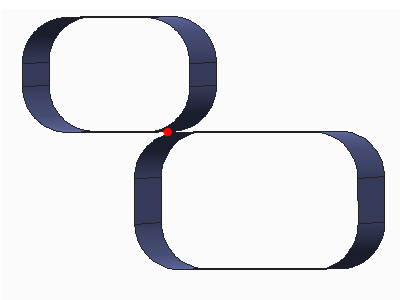
When you design a cam-follower connection, it may be helpful to visualize the cams as two-dimensional figures in the working plane. You will get better results if the two cams make contact at some point in the working plane. Try to avoid a design with a connection along a line in the working plane.
In the following table in the figures, assume that the working plane coincides with the viewing plane. The extrusion direction is into (perpendicular to) the viewing plane. In the left image, the connection between the two cams in the working plane occurs at a point. In the three-dimensional view, the connection is a line that is perpendicular to the working plane.
In the right image, the connection between the two cams in the working plane occurs at a line that is in the working plane. In the three-dimensional view, the connection is along a plane.
|
Acceptable Contact
|
Unacceptable Contact
|
 |
 |
Design Principles
Keep in mind:
• For better results, model your cams (in three dimensions) so they contact along a line that is perpendicular to the working plane. Avoid having flat surfaces on both cams.
• To ensure correct and reliable behavior, the working planes containing the two-dimensional cams should always remain parallel. Define constraints or additional connections between the cam bodies to keep the extrusion directions parallel.