Pulling Walls
Use the Pull Wall tool to move walls and attached geometry perpendicular to the bend line and on the plane of the wall. Reliefs, seams, and adjacent geometry are included by default in the pull operation. You also have the option to do the following:
• Recreate, remove, or change to the default option for bend reliefs, corner reliefs, and corner seams.
• Include or exclude holes, cuts, and forms on adjacent walls and the fixed geometry reference in the pull operation.
• Extend neighboring surfaces.
Follow the steps below to pull walls.
4. Click  .
.
.Selecting References
1. In an open sheet metal part with bends, click >  Pull Wall. The Pull Wall tab opens.
Pull Wall. The Pull Wall tab opens.2. The fixed geometry reference is selected and highlighted, click one or more surfaces to select the walls to pull.
To change the fixed geometry reference, click the collector, right-click and select Remove. Select a new reference. |
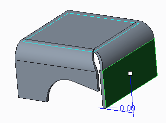
The following figure shows a sheet metal part before the pull operation.
3. Type a number in the  box or use the dragger in the graphics window to set the pull length.
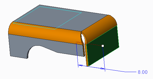
box or use the dragger in the graphics window to set the pull length.The following figure shows the same part being pulled using the default adjacent conditions.
4. To flip the pull direction, click  or right-click and select Flip Pulling Direction.
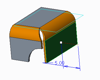
or right-click and select Flip Pulling Direction.The following figure shows the same part when the wall is pulled in the opposite direction.
Setting Adjacent Conditions
To set adjacent conditions use the right-click menu or click the Adjacent Conditions tab. Use the Adjacent Conditions options to do the following:
1. Remove the bend reliefs or change them to Rip reliefs.
2. Remove corners reliefs or change them to V Notch reliefs.
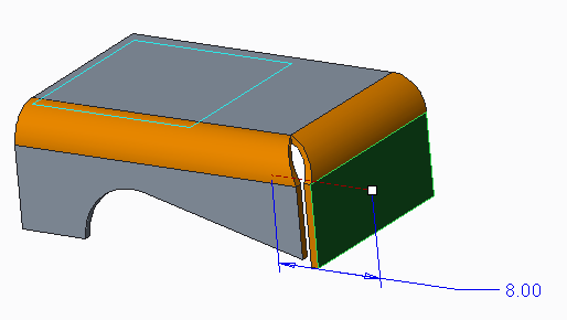
The following figure shows the same part being pulled without recreating corner reliefs. By default when you clear the Recreate Corners check box, you cannot recreate corner seams or extend neighboring side surfaces.

3. Remove corner seams or change them to Open corner seams.
The following figure shows the same part being pulled recreating corner reliefs but without recreating corner seams.

4. Extend neighboring side surfaces.
The following figure shows the same part being pulled when you click to select the Extend neighboring side surfaces check box.
5. To specify whether to recreate round or chamfer geometry adjacent to recreated corner seams, click the Create round/chamfer geometry check box. Rounds or chamfers are recreated in the new location.
Including Cuts and Forms
To include cuts and forms on the fixed geometry reference in the pull wall operation use the Options tab.
1. Click to activate the Move additional items collector.
2. Select the cut surfaces, form surfaces, punch axis points, and projected curves and coordinate systems with follow options to include in the pull wall operation.
You can select items individually or use box selection to select multiple items. |
Changing Properties
To change feature properties, use the Properties tab.
1. To edit the feature name, type a new one in the Name box.
2. To display information on the feature in the browser, click  .
.
.