Changing and Updating Material Codes
Use the sample files provided at <Creo load point>\Common Files\help\sample_models\piping when working in this exercise. It is recommended that you create a copy of the piping folder on your computer and set up piping data before you start working with the tutorial.
Workflow
1. Create an Auto-Selection file.
2. Update the Specification Directory file.
3. Create a pipe segment.
Create an Auto-Selection File
1. On the Home tab, click  New. The New dialog box opens.
New. The New dialog box opens.2. Under Type, click  Assembly.
Assembly.3. Click OK to create a new assembly.
4. Click >  Piping. The Piping tab opens.
Piping. The Piping tab opens.5. On the Piping tab, select the Spec Driven check box.
6. Click  Spec DB. The Define Piping Specification dialog box opens.
Spec DB. The Define Piping Specification dialog box opens.7. Click to create a new file. The New File dialog box opens.
to create a new file. The New File dialog box opens.8. Under Type, select Auto-selection file.
9. In the Name box, type 1.
10. Click OK to open the file.
11. Under Select Stock Number Format, perform the following action:
◦ In the Keyword box, select MATL_CODE.
12. Under Select Material Classification Code Format, perform the following actions:
a. In the Keyword box, select MATL_CODE.
b. In the Delimiter box, select _.
c. In the Keyword box, select SCH_RATE.
d. In the Delimiter box, select _.
e. In the Keyword box, select SIZE.
13. Click  to add the displayed record to the Auto-Selection file.
to add the displayed record to the Auto-Selection file.14. Click  to save the Auto-Selection file.
to save the Auto-Selection file.15. Click  to close the current file.
to close the current file.Update the Specification Directory File
1. Click  . The Open File dialog box opens.
. The Open File dialog box opens.2. Double-click piping_spec_dir.csv to open it.
3. In the Specification box, type 1.
4. In the Layer box, type 1_layer.
5. Click next to Auto Selection. The Open dialog box opens.
next to Auto Selection. The Open dialog box opens.6. Double-click 1.ptd to select it.
7. Click to add the displayed record.
to add the displayed record.8. Click to save the file.
to save the file.9. Close the Define Piping Specification dialog box.
Create a Pipe Segment
1. Click  Create Pipe. The Create Pipeline dialog box opens.
Create Pipe. The Create Pipeline dialog box opens.2. In the Specification box, select 1.
3. In the Size box, select 100A.
4. In the Number box, type abc.
5. In the Create SubAssembly box, select STEAM-ABC.
6. Click OK. The Create Pipeline dialog box closes.
7. Click  Set Start. The Define Start dialog box opens.
Set Start. The Define Start dialog box opens.8. Select ASM_DEF_CSYS in the graphics window.
9. Click OK. The Define Start dialog box closes.
10. Click  Extend. The Extend dialog box opens.
Extend. The Extend dialog box opens.11. Drag a dragger handle along the z-axis and click Apply. A pipe segment is created.
12. Click Cancel. The Extend dialog box closes.
13. Click  Piping Info. The Report Pipeline dialog box opens.
Piping Info. The Report Pipeline dialog box opens.14. Under Type, click  to display the pipeline report.
to display the pipeline report.15. Select the pipe segment in the graphics window.
16. Click OK on the Select dialog box. The INFORMATION WINDOW opens.
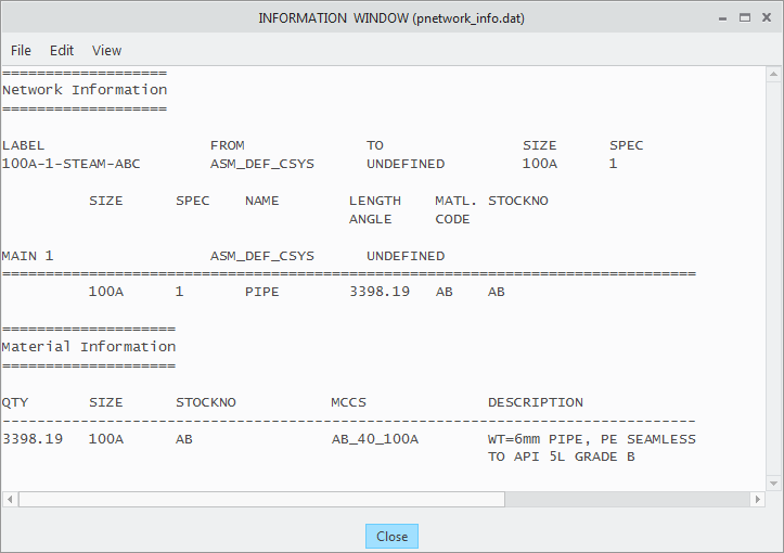
The values for MCCS and STOCKNO are per the values defined while creating the pipeline. |
17. Close the INFORMATION WINDOW and the Report Pipeline dialog box.