Adding a New Fitting Size
Use the sample files provided at <Creo load point>\Common Files\help\sample_models\piping when working in this exercise. It is recommended that you create a copy of the piping folder on your computer and set up piping data before you start working with the tutorial.
Workflow
1. Add new size to the fitting generic part.
2. Export fitting parameters to a CSV file.
3. Add new size to the Fitting catalog.
4. Update Bolt Nut Selection data.
5. Define a new size in the Piping catalog.
6. Define a new pipe size and fitting size in Auto-Selection file.
7. Route a pipe segment.
8. Insert the fitting with the new size.
Add New Size to the Fitting Generic Part
1. Open the piping folder and set the piping_assembly folder as the Working Directory.
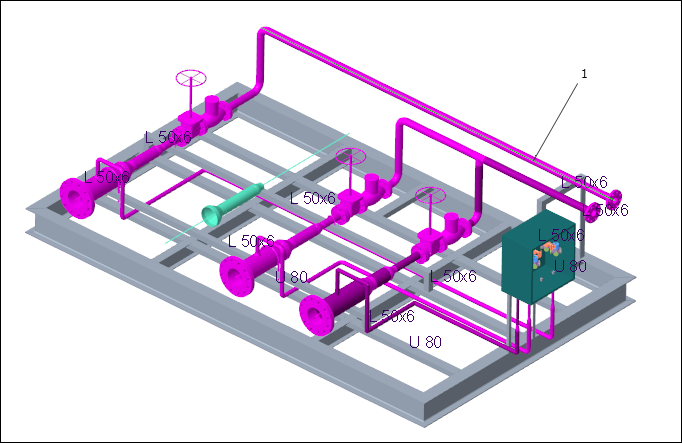
2. Open manifold_skid.asm.
3. Click >  Piping. The Piping tab opens.
Piping. The Piping tab opens.4. Click  and clear the Pipeline View check box.
and clear the Pipeline View check box.5. Right-click FLANGE_NECK_RF-STEEL-30K-150<FLANGE_NECK_RF>.PRT in the graphics window or on the Model Tree and select Open Generic.
The selected flange is highlighted in the graphics window.
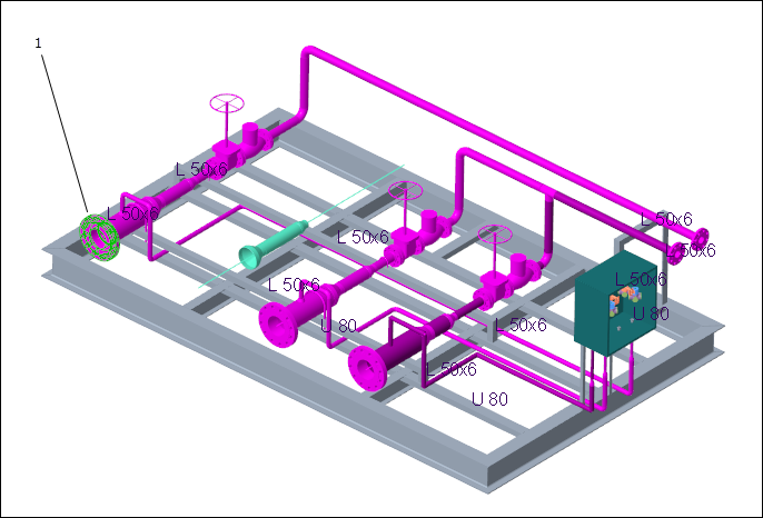
1. Flange
6. Click Open on the Select Instance dialog box. The FLANGE_NECK_RF window opens.
7. Click > >  Family Table.
Family Table.8. Click  to insert a new instance to the family table.
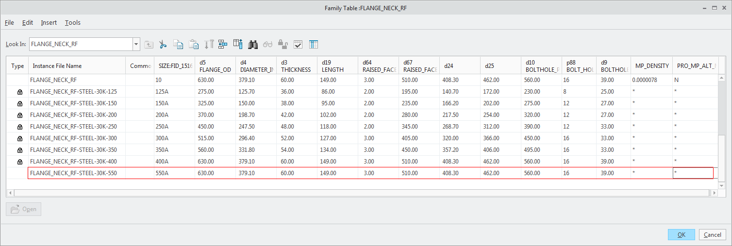
to insert a new instance to the family table.9. Type the following values in the new instance:
Instance File Name | FLANGE_NECK_RF-STEEL-30K-550 |
Common Name | |
SIZE: FID_1516 | 550A |
d5 FLANGE_OD | 630.00 |
d4 DIAMETER_IN | 379.10 |
d3 THICKNESS | 60.00 |
d19 LENGTH | 149.00 |
d64 RAISED_FACE_HEIGHT | 3.00 |
d67 RAISED_FACE_DIAMETER | 510.00 |
d24 | 408.30 |
d25 | 462.00 |
d10 BOLTHOLE_PITCH_CIRCLE_DIA | 560.00 |
d88 BOLT_HOLE_NUM | 16 |
d9 BOLTHOLE_DIA | 39.00 |
MP_DENSITY | |
PRO_MP_ALT_MASS |
In the following image, newly added values are highlighted:
10. Click  to verify instances of the family. Click Verify in the Family Tree dialog box. Click Close when the verification status of the newly added instances is Success.
to verify instances of the family. Click Verify in the Family Tree dialog box. Click Close when the verification status of the newly added instances is Success.11. In the Family Table dialog box, select the instance FLANGE_NECK_RF-STEEL-30K-550A and click  Open. The fitting with the new values appears. Close the window.
Open. The fitting with the new values appears. Close the window.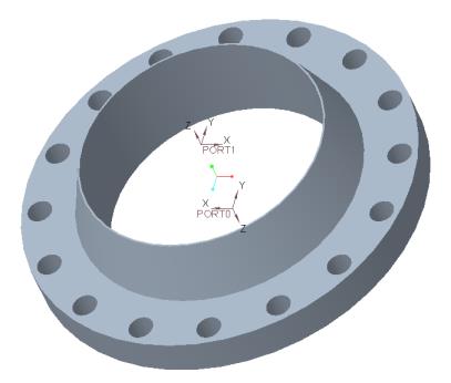
12. Click  to save the updated fitting model.
to save the updated fitting model.Export Fitting Parameters to a CSV File
1. Switch to the MANIFOLD_SKID.ASM window.
2. Click > Piping. The Piping tab opens.
Piping. The Piping tab opens.3. Click > . The Export Fitting Catalog File dialog box opens.
4. Click next to Fitting Model Files. The Open dialog box opens.
next to Fitting Model Files. The Open dialog box opens.5. Click the In Session folder and open the flange_neck_rf.prt file.
6. In the csv File Name box, type flange_neck_rf_new.
7. Click next to Destination and select Desktop as the destination folder. You can also select any other location.
next to Destination and select Desktop as the destination folder. You can also select any other location.8. Click OK to export the fitting parameters to a CSV file.
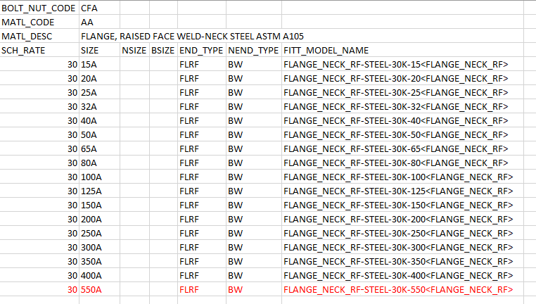
In the following image, newly added values are in red:
Add New Size to the Fitting Catalog
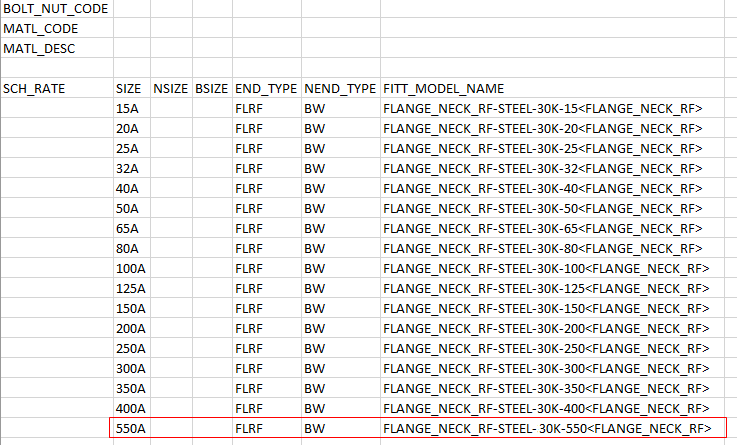
1. In the master_catalog folder, double-click the fitting folder, and open the flange_neck_rf.csv file.
2. Insert a row and then copy the newly added values from the exported CSV file to the row.
3. In the SCH_RATE column, type 30.
In the following image, newly added values are in red:
4. Save and close the Fitting master catalog file.
5. Close the flange_neck_rf_new.csv file.
Update Bolt Nut Selection Data
1. In the master_catalog folder, open the piping_bolt_nut_select.csv file to add the new size:
BOLT_NUT_CODE | SIZE | SCH_RATE | MCCS_CODE | QUANTITY | BULK_ITEM_NAME |
|---|---|---|---|---|---|
CFA | 550A | 30 | 311AB40550 | 24 | 311AB40550<BOLT_NUT_BULK> |
In the following image, newly added values are in red:
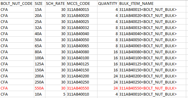
The material classification code (MCCS) is assigned to the fitting as per its size and rating. |
2. Save and close the Bolt Nut Selection file.
3. Click >  Open. The Open File dialog box opens.
Open. The Open File dialog box opens.4. Click the In Session folder and open bolt_nut_bulk.prt file.
5. Select The generic in the Select Instance dialog box and click Open. The Relations dialog box opens.
6. Click Family Table.
7. Click to insert a new instance to the family table.
to insert a new instance to the family table.8. Type the following values in the new instance:
Instance File Name | Common Name | BOLT_DIA | BOLT_LENGTH | MATERIALDESC |
|---|---|---|---|---|
311AB40550 | BOLT NUT ASTM CS 106 |
In the following image, newly added values are highlighted:
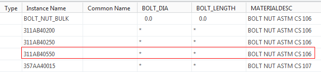
The material classification code (MCCS) defined previously is added as an instance in the bolt_nut_bulk.prt file. |
9. Click to verify instances of the family. Click Verify in the Family Tree dialog box. Click Close when the verification status of the newly added instances is Success.
to verify instances of the family. Click Verify in the Family Tree dialog box. Click Close when the verification status of the newly added instances is Success.10. Click OK to close the family table.
11. Click > in the Relations dialog box to save the changes.
12. Click OK to close the Relations dialog box.
Define a New Size in the Piping Catalog
1. In the master_catalog folder, double-click the pipe folder, and open the pipe_steel.csv file.
2. Insert a row and add the following values to the catalog file:
SCH_RATE | SIZE | SIZE_CODE | PIPE_OD | PIPE_THK | END_TYPE |
40 | 550A | 550 | 558.8 | 12.7 | PE,BE |
In the following image, new pipe size values are in red:
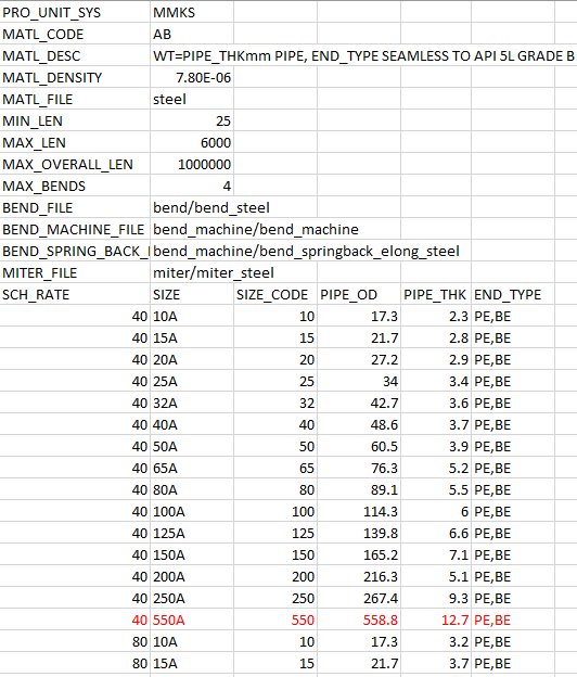
3. Save and close the Pipe master catalog file.
Define a New Pipe Size and Fitting Size in Auto-Selection File
1. Click >  Spec DB. The Define Piping Specification dialog box opens.
Spec DB. The Define Piping Specification dialog box opens.2. Click . The Open File dialog box opens.
. The Open File dialog box opens.3. Double-click ms_asfile.ptd. The selected file populates the Define Piping Specification dialog box.
4. In the Pipe tab, select 40 in the Schedule box.
5. Click  .
.
.6. Select 550A and click OK to add the new pipe size.
7. Click  to add the record to the Auto-Selection file.
to add the record to the Auto-Selection file.8. Click  to save the record.
to save the record.9. Click the Fitting tab. The information of all the fittings in the assembly appears under Select Record.
10. In the Select Record box, select FLANGE NECKFLANGE fitting/flange_neck_rf AA 30 FLRF BW SNAME,MATL_CODE,SCH_RATE,END_TYPE,-,SIZE_CODE 33,MATL_CODE,SCH_RATE,SIZE_CODE FLANGE CFA.
11. Click .
.12. Select 550A and click OK to add the new fitting size.
13. Click to add the record to the Auto-Selection file.
to add the record to the Auto-Selection file.14. Click to save the record.
to save the record.15. Close the Define Piping Specification dialog box.
Route a Pipe Segment
1. Click Route Pipe.
Route Pipe.2. Select a pipe segment in the graphics window. A warning message opens.
1. Pipe segment
3. Click Confirm in the warning message.
4. Click  Set Start. The Define Start dialog box opens.
Set Start. The Define Start dialog box opens.5. Click > >  Coordinate System.
Coordinate System.6. Select ASM_DEF_CSYS at the corner of the skid as the Reference.
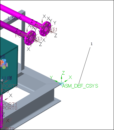
1. Coordinate system
7. In the Size box, select 550A.
8. Click OK.
9. Click >  Extend. The Extend dialog box opens.
Extend. The Extend dialog box opens.10. Drag a dragger handle along the z-axis.
11. Click OK. The new pipe segment of the size 550A is added.
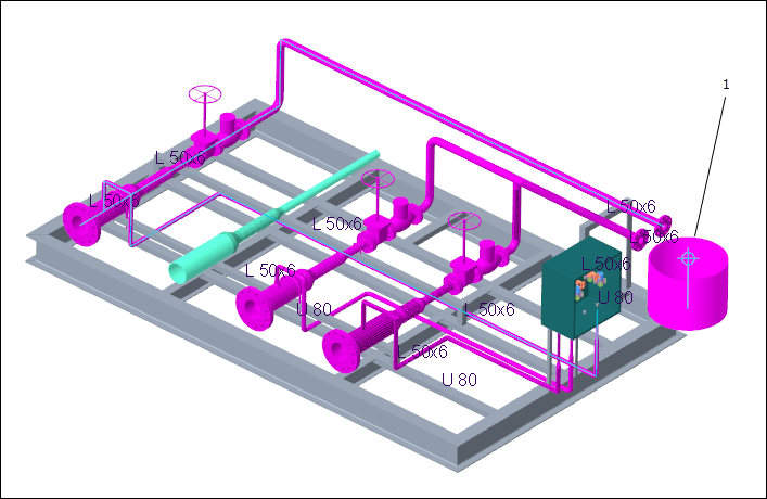
1. New pipe segment
Insert a Fitting with the New Size
1. Click  Insert Fitting. The Insert Fitting dialog box opens.
Insert Fitting. The Insert Fitting dialog box opens.2. Select a reference on the newly added pipe segment.
3. In the Fitting field, select  .
.
.4. Click OK. The flange fitting of the size 550A is inserted.
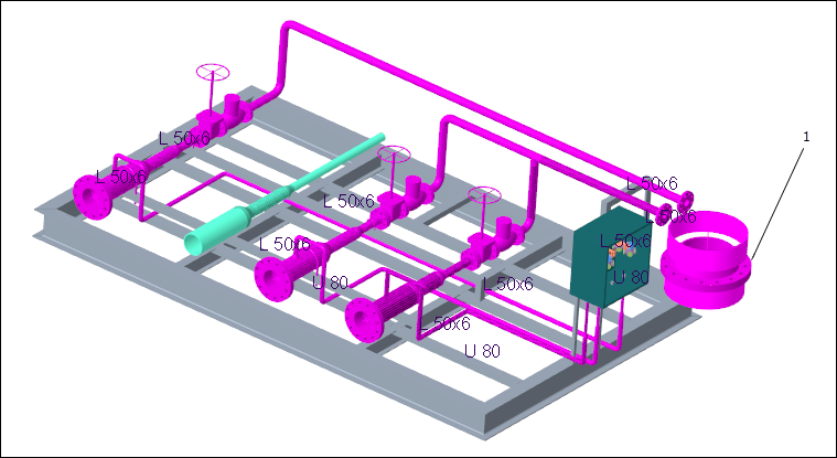
1. Flange fitting with the new size