Checking the Clearance between the Pipe Cuts with Flanged Fittings
You can cut a set of pipe runs parallel to the reference pipe run in a single operation. All cuts are created at locations identical to locations on the reference pipe run. If a target run is very close to the reference run or another target run, and the cut is created at an identical location, the flange fittings attached to the parallel cuts may interfere with each other and result in clash depending on the available clearance.
To avoid such clashes, Spec-Driven Piping automatically checks the clearance based on the minimum clearance value for the joint fitting. Use the piping_joint_fitting_clearance configuration option to specify the default value for the minimum clearance. Specify the value in the current assembly units.
The identical cut locations on the parallel pipe runs can be staggered based on the status of clearance checking.
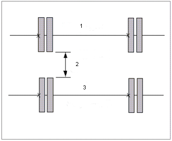
The following figure shows the alignment of the pipe cut locations between pipe runs A and B, where the spacing between the joint fittings on pipe run is greater than the minimum clearance value.

1. Pipe run A
2. Actual clearance
3. Pipe run B
In the preceding example, the actual clearance is greater than the minimum clearance value. Therefore, the cuts and joint fittings are aligned one below the other.
If the actual clearance is less than the specified minimum clearance, the cuts on the target pipe runs are staggered by the value specified for the offset distance.
Staggering of Cuts With Joint Fitting
To avoid a clash due to inadequate clearance between joint fittings, cuts can be staggered during the cutting of parallel pipes.
The value specified for Offset Distance on the Cut Pipe dialog box for the parallel pipes is used to stagger the cuts. When a joint fitting interference is detected, the fitting that is causing the violation is highlighted. You are prompted to stagger the cut location. Select Yes to insert the staggered cut or select No to abort the cut insertion. Further, if you have chosen to insert the staggered cut and the resultant staggered location also violates the clearance check, you are prompted whether to continue or abort the cut insertion. If you select Yes, the cut is inserted at the staggered location and if you select No the cut insertion is aborted.
Use the piping_joint_fitting_offset configuration option to specify the default offset value. Specify the offset value in the current assembly units.
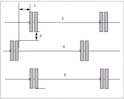
The following figure shows a pipe cut stagger between pipe runs A, B, and C as the spacing between the joint fitting on these pipe runs is less than the minimum clearance value.

1. Offset
2. Pipe run A
3. Actual clearance
4. Pipe run B
5. Pipe run C
In the preceding figure, the cut locations on adjacent pipe runs, that is, pipe run A and pipe run B are staggered. The cut locations on alternate pipe runs, that is, pipe run A and pipe run C are aligned.