Fitting Ports
About Fitting Ports
A fitting port is a standard coordinate system feature (CSYS) on the fitting. Its origin represents:
• The location at which a pipe is physically welded to a fitting, as in butt-welded or branchlet fittings.
• The location up to which the pipe extends into the fitting, as in socket-welded and screwed fittings.
• The location up to which the pipe extends inside a fitting, as in flange fittings.
• The location of a flange face that mates with another flange face.
• The start point of a routed segment.
Fitting Port Creation for Branch Outlet Fittings
The branch outlet fitting must have an inlet port and outlet ports as shown in the following figures.
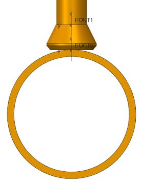
The inlet port of the fitting is aligned with the surface of the main pipe segment as follows:
• The z-axis of the outlet port of the fitting is aligned with the branch pipe segment, if an existing junction is identified for the fitting insertion.
• In orthogonal branch outlet fittings, the z-axes of inlet and outlet ports are parallel to each other. The non-orthogonal branch outlet fittings such as latrolets, have an angle between the z-axes of the inlet and the outlet ports. Based on this, lateral fittings are distinguished from other branch outlet fittings.
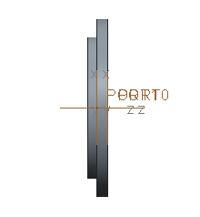
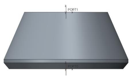
Port Location for Fittings with Butt Welded/Flanged Ends
In the following graphic, the arrow shows the pipe contact location.
For butt-welded fittings, the pipe is welded to the butt-welded ends of the fitting. The fitting ports are located at the butt-welded ends as shown in the figure. If a butt-welded fitting has two butt-welded ends along its local z-axis, then either end can be defined as the inlet port.
For flanged fittings, the flanged face of the fitting mates with a matching gasket or a suitable flanged face of another fitting. The fitting ports must be located at the flanged face as shown in the figure. If a flanged fitting has two flanged ends along its local z-axis, then either end can be defined as the inlet port. The positive z-axes of the inlet and outlet ports are pointing outward of the fitting and are aligned to the fitting local z-axis.
The two ports need not be created in any particular sequence and their names are user-definable. Of the two ports, one must be defined as the inlet port. By convention, the port with the SIZE parameter is defined as the inlet port. |
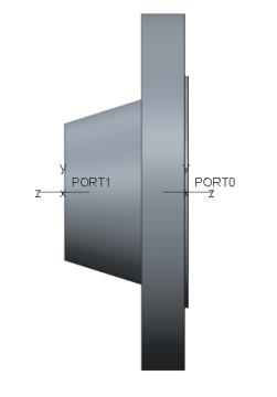
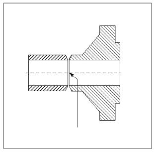
Port Location for Fittings with socket Welded/Threaded Ends
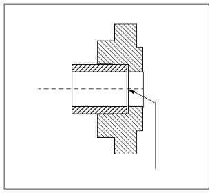
For fittings with socket-welded or threaded ends, the pipe extends up to the origin of the port that represents the end of the socket or the threaded hole. The arrow in the following figure points to the pipe contact location.
In the following figure, PORT1 is located on the inside face of the socket, and PORT0 (a flanged end) is located on the outside flange face. For threaded fittings, the pipe is threaded up to the origin of the port that represents the end of the threaded hole or socket.