About the Chamfer Feature
A chamfer is a feature in which you bevel an edge or corner. Surfaces can be any combination of solid model surfaces and quilts. You can create two types of chamfers: corner chamfers and edge chamfers.
Corner Chamfers
You create corner chamfers using the  Corner Chamfer tool. When you create a corner chamfer, you select a vertex defined by three edges, and then you set length values along each chamfer direction edge.
 Corner Chamfer tool. When you create a corner chamfer, you select a vertex defined by three edges, and then you set length values along each chamfer direction edge.
The documentation refers to edge chamfers as chamfers, and corner chamfers as corner chamfers. |
Edge Chamfers
You create edge chamfers using the  Edge Chamfer tool. To create edge chamfers, you define one or more chamfer sets. A chamfer set is an organizational unit containing one or more chamfer pieces (chamfer geometry). After you specify chamfer placement references, the system uses default attributes, distance values, and default transitions that best fit the referenced geometry to create the chamfer. The system displays preview geometry of the chamfer in the graphics window, enabling you to create and modify both chamfer pieces and transitions before feature creation. Note that the default settings accommodate most modeling cases. However, you can define the chamfer sets or transitions to achieve the preferred chamfer geometry.
 Edge Chamfer tool. To create edge chamfers, you define one or more chamfer sets. A chamfer set is an organizational unit containing one or more chamfer pieces (chamfer geometry). After you specify chamfer placement references, the system uses default attributes, distance values, and default transitions that best fit the referenced geometry to create the chamfer. The system displays preview geometry of the chamfer in the graphics window, enabling you to create and modify both chamfer pieces and transitions before feature creation. Note that the default settings accommodate most modeling cases. However, you can define the chamfer sets or transitions to achieve the preferred chamfer geometry.
Anatomy of an Edge Chamfer
An Edge Chamfer consists of the following:
• Sets—Chamfer segments that consist of unique attributes, geometric references, and plane angles, and one or more chamfer distances: legs of the triangle formed by the chamfer and the neighboring surfaces.
• Transitions—Filler geometry that connects chamfer pieces. Transitions are located where the chamfer pieces or set ends meet or terminate. The system uses default transitions during the initial chamfer creation and provides many transition types, allowing you to create and modify transitions.
Chamfer Sets and Transitions
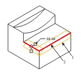
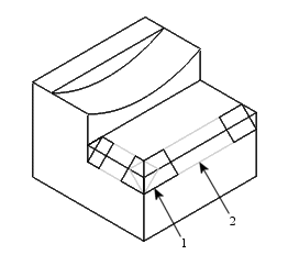
Set Mode Display | Transition Mode Display |
|---|---|
Two edge references are selected for the chamfer set. Preview geometry of the two chamfer pieces and the distance value is shown. | All transitions for the entire edge chamfer feature are displayed. The two chamfer pieces are shown for context. |
 1. Chamfer piece 2. Edge reference |  1. Transition 2. Chamfer piece |