To Define Lattice Transitions
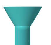
The purpose of using transitions is to improve printability of a model that contains a beam-based lattice structure, by adding transition beams between the lattice and the internal horizontal walls (ceiling) of the bounded lattice volume. Define the transition between the beam-based lattice and a wall as part of the procedure to create beam-based lattice.
1. Click the Transition tab.
2. To select the type of transition beams between the lattice and the wall of the model, next to Transition type, select an option:
◦ None—Do not create transition beams.
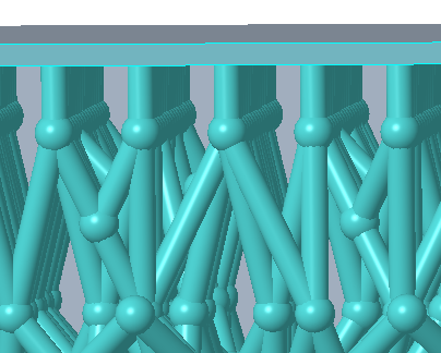
◦ Vertical—Create transition beams that contain an elbow, so that the transition beams are vertical at the supported point in the model wall.
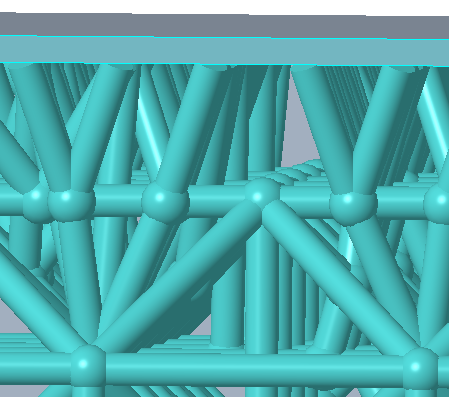
◦ Slanted—Create transition beams that slant from an elbow in the lattice to the supported point in the model wall.
When you select vertical or slanted transition type, define the parameters that follow. The set of parameters differs slightly depending on the type.
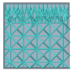
3. To define the critical angle for the walls of the internal bounded volume of the lattice structure, next to Critical angle, type an angle value. Additional transition beams are added between the lattice and the supported wall in areas where the angle between the normal to the surface and the build direction is below the critical angle.

Critical angle 30

Critical angle 45

Critical angle 75
4. To define the distance on the wall that can be 3D printed without the additional support of transition beams, next to Max. unsupported distance, type a distance value.
This is the maximum horizontal distance between the attachment points, relative to the build direction, in the areas that do not contain support beams after the transition beams are created. This parameter defines the spacing between the attachment points of the supporting beams. Beam thickness is also considered for the spacing calculation. Tapered ends of beams follows the same formula for spacing calculation, though the unsupported area is expected to be far smaller.
5. To define the minimal length of the transition beams, or of the beams of the original lattice that are split due to transition beam creation, next to Targeted min. beam length, type a length value.
This parameter controls the shape of the supporting structure. A small value produces better branching, but it can lead to slower performance.
This is an advisory parameter. If a supporting beam cannot accommodate this parameter for a supporting beam, the system disregards this constraint and constructs the beam anyway.
6. To define the maximal length of the transition beams, next to Max. beam length, type a distance value. This parameter is important for printability, so the system enforces it.
7. To define the minimal allowed angle between transition beams that share a common junction, next to Targeted min. angle between beams, type an angle value. Set large values to ensure printability.
8. For vertical transition beams without tapered ends, to define the distance from the supported point in the model wall to the elbow in the transition beam that connects to the transition beam structure, next to Distance to elbow, type a distance value.
9. For vertical transition beams, to cover the maximum ceiling area with support by tapering the transition beams in the layer closest to the ceiling, select the Taper end of beams check box.