To Create Stochastic Lattice
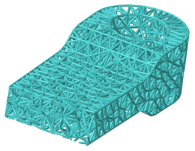
Stochastic lattice is created by randomly distributed points connected by beams inside volumes or over surfaces. After you define the lattice, you see a preview. You can redistribute the points to get a different result.
The cell parameters are interdependent, so some of them might change during calculation.
1. Click >  Lattice. The Lattice tab opens.
Lattice. The Lattice tab opens.2. On the Lattice tab, define these settings:
a. Next to Lattice type, select Beams.
b. To set the size of the lattice relative to the current size of the cell, type a value in the  scale box, and press ENTER.
scale box, and press ENTER.4. For lattice that does not replace a body, you can define the body to which the feature is added. Click the Body Options tab, and perform one of the following actions:
◦ To add geometry to an existing body, click the body collector, and then select the body to which geometry is added.
◦ To create the feature in a new body, select the Create new body check box. The name of the new body appears in the body collector.
5. Click the Cell Type tab, and define the structure of the lattice cells. These parameters are interdependent, and the actual values might change during calculation.
a. Under Cell Shape, select  Stochastic.
Stochastic.b. To set the algorithm used to generate the stochastic lattice, select an option:
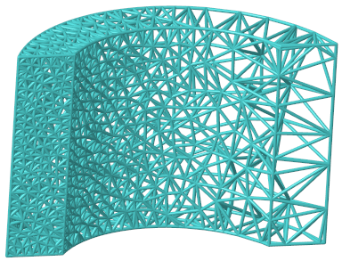
▪ Delaunay triangulation—Generates tetrahedrons. Creates a strong, light structure. Conforms well to edges.
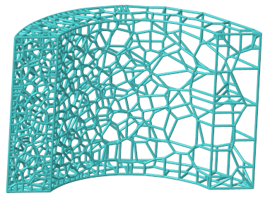
▪ Voronoi diagram—Generates convex polyhedrons with many faces. Conforms smoothly to surfaces.
c. To define the location to create lattice, select an option:
▪ Inside volume—In the inside volume of the model or lattice volume region.
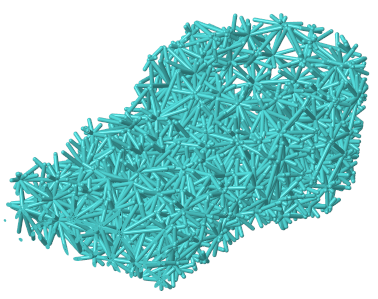
▪ On bounding surfaces—Over the bounding surfaces of the model or lattice volume region.
▪ Volume + bounding surfaces—Over the bounding surfaces and in the inside volume of the model or lattice volume region.
d. To set the method for defining cells, select an option:
▪ Target cell size—Defines the lattice cell size measured diagonally across the bounding box of the cell.
▪ Number of cells—Defines the total number of cells in the lattice volume. If On bounding surfaces is selected, then only the intersection of the stochastic lattice with the model surface is displayed. This intersection contains fewer cells, because some of the cells are located completely inside the volume.
The parameters Number of cells, Min. beam length, and Max. beam length can contradict each other. If you set Number of cells, this basically defines the typical cell size and typical beam length.
e. To set the minimum length for lattice beams, type a value in the Min. beam length box.
f. To set the maximum length for lattice beams, type a value in the Max. beam length box.
Using Min. beam length or Max. beam length greatly increases the calculation time, and in some cases it is not possible to generate the lattice. If you set one or both of these parameters, it is recommended to set the Max. beam length at least 10 times the Min. beam length, and 20 times the Min. beam length is even better.
g. Optionally, to recalculate the random distribution of the points on which the lattice structure is based, click Randomize.
6. Click the Cell Fill tab, and define the structure of the beams:
a. To set the size of the beam cross section, type a value in the Cross section size box.
b. To add balls where the beams intersect and in the center of the cells, select the Ball diameter check box.
c. To set the diameter of the balls, type a value in the Ball diameter box.
d. For lattice created by replacing solid with lattice, to remove beams that are not attached to a solid or another beam at both ends of the lattice, select the Remove dangling beams check box.
e. To trim the beams at the boundary of the lattice, select the Trim boundary check box.
Trimming the boundary of the lattice will happen only in the physical model. You will not see the trim effects in the CAD model.
7. Click the Density tab, and define regions of varied distribution of points within the lattice volume, and their adaptive distribution parameters:
a. Under Adaptive distribution, click New set. The References collector becomes available.
b. Select a reference from which distance is measured:
▪ Point—Defines a spherical volume region, with a radius equal to the distance value.
▪ Curve—Defines a cylindrical sweep volume region, with a radius equal to the distance value.
▪ Surface, quilt, axis, edge, vertex, or coordinate system origin—Defines a volume region that is offset by the distance value.
c. To set the distance from the reference where the density changes, type a value in the Distance box. This distance determines the size of the volume region.
d. To set the density at the selected reference, type a value in the Density ratio box.
e. To set the rate of change of the density, type a value in the Density change rate box.
When the rate = 1, the rate of change is linear.
When the rate < 1, the rate of change is less than linear.
When the rate >1, the rate of change is greater than linear.

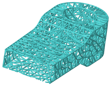
In the image, the surface on the left is the reference, and the density is greater near the reference.
8. Click  OK. The stochastic lattice is created.
OK. The stochastic lattice is created.9. Optionally, to redistribute the random distribution of points:
a. In the Model Tree, click the Lattice feature and select  Edit Definition from the shortcut menu.
Edit Definition from the shortcut menu.b. Click the Cell Type tab, and click Redistribute.