To Create an Ear Feature
An ear is a protrusion that is extruded along the top of a surface and can be bent at the base.
1. Set the allow_anatomic_features configuration option to yes to make the Ear command available on the All Commands list.
2. Add the Ear command to the desired user-defined group on the ribbon.
|
|
For information about customizing the ribbon, see the Related Links.
|
3. Click Ear. The OPTIONS menu appears.
4. Select the type of ear feature you want, then click Done.
◦ Variable—The ear is bent at a user-specified, modifiable angle, measured from the surface from which the ear is extruded.
◦ 90 deg tab—The ear is bent at 90°. No dimension is created for the angle.
5. Select a sketching plane that is perpendicular to the surface to which the ear will be attached. If needed, click Flip reverse the direction of feature creation.
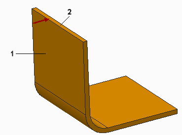
1. Surface that is reference for sketching plane
2. Surface to which ear will be attached
6. Click Okay. The SKET VIEW menu appears.
7. Select a sketch view. The Sketch tab opens.
8. Sketch the ear.
◦ The section must be open, with the endpoints aligned to the surface to which the ear will be attached.
◦ The entities that are attached to the surface must be parallel to each other, perpendicular to the surface of attachment, and long enough to accommodate the bend.
9. Click  OK. A box to enter the ear depth appears.
OK. A box to enter the ear depth appears.10. Type a value for the depth, the thickness of the ear, and click  . A box to enter the bend radius appears.
. A box to enter the bend radius appears.11. Type a value for the bend radius The radius of the bend is measured from the sketching plane out of the screen. Click . A box to enter the bend angle appears.
. A box to enter the bend angle appears.12. Type a value for the bend angle, and click . The ear is created.
. The ear is created.You can redefine ears from one type to another. The dimensioning of the two ear types is:
• Variable ear—The length of the sketched section represents the overall length of the inside edge (including the length of the bent portion).
• Tab—The length of the sketched section represents the distance between the bottom and the top of the outside edge (including the projection of the bent portion on the plane of the straight portion).