Using Bounding Edges
When you create a Creo Flexible Modeling feature, you can set bounding edges to control options for attaching changed geometry. Bounding edges determine which surfaces in the model, in addition to modified geometry and their neighbors, are extended in order to solve the feature. The bounding edges and the changed geometry must be selected from the same body or quilt.
There are two types of bounding edges, default bounding edges that the system uses to determine the current solution, and user-defined. If you define edges to use as bounding edges, the default bounding edges are not used to find solutions.
Default bounding edges are displayed in turquoise only if they contribute to the solution. User-defined bounding edges are always displayed in turquoise.
You can set bounding edges when you create or edit the following Creo Flexible Modeling features:
• Move
• Offset
• Modify Analytic
• Mirror
• Substitute
• Attach
In the figure below, a boss is selected so it can be rotated around an axis using the Move tool.
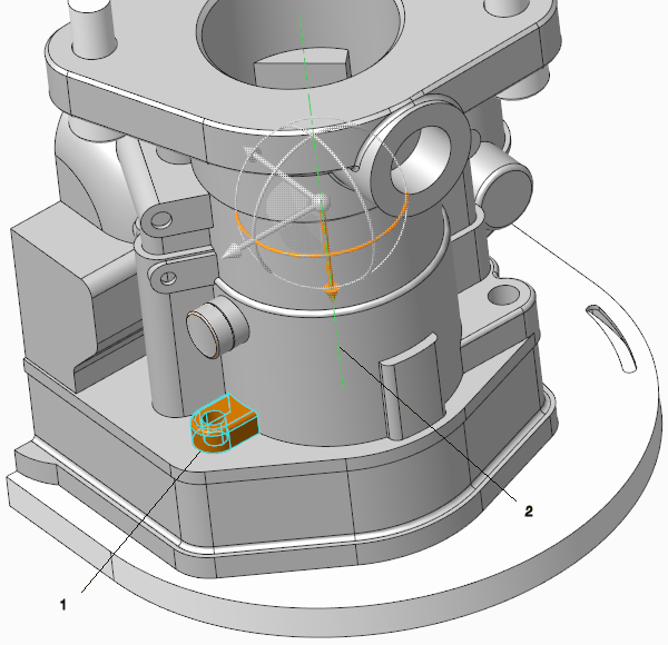
1. Original geometry
2. Axis
In the figure below, the geometry selection is rotated without setting bounding edges. The rotated selection automatically extends to the surface in the new location.

1. Original geometry
2. Rotated geometry
In the figure below, bounding edges were selected and the rotated geometry extends to the plane that is defined by the extension of one of the surfaces that define the bounding edge.
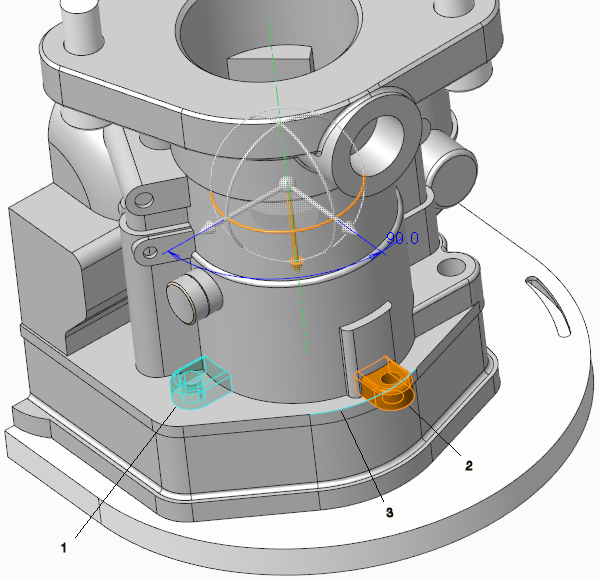
1. Original geometry
2. Rotated geometry
3. Bounding edge