Setting Analysis Parameters
You can set the analysis parameters and start the automatic creepage and clearance computation in the Analysis tab of the Clearance and Creepage Analysis dialog box.
The distances to cover between the net pairs and the groove width must be available for the computation engine to apply for creepage. Industry standards usually define these values based on factors such as the voltage difference and the insulation class used. There are different standards for different regions or environments. An electric assembly may need to be tested against many different analysis parameters. You can manage multiple analyses in a single session by defining different configurations.
A configuration refers to a specific set of analysis parameters that is the creepage distance, clearance distance, and the groove width between each net pair.
To Add a New Analysis Configuration
1. Right-click the Configuration box and select Add Configuration.
2. Right-click New Configuration and select Rename Configuration. The Choose new name for configuration box appears.
|
|
• You can specify the name of the regulation such as, IEC 60664 or UL 60950-1, as the configuration name.
• For each new configuration, you receive a new set of parameters, while the results of previously analyzed configurations remain in the session.
|
3. Type the name of the configuration and click  .
.
.4. Specify the analysis parameters for the configuration.
5. In the Violation Tolerance box, type or select a value.
Specifying Analysis Parameters for a Configuration
You can use custom values or standard tables to specify analysis parameters for a configuration.
Using Custom Values
1. Select Custom Values to specify the distance values and the groove width parameters for each net pair.
2. Click Select Source and select a net of type Potential in the graphics window. All the target nets of type Potential and Grounded are listed in the dialog box.
3. Add distance values for clearance, creepage, and the groove width for each target net.
You can assign the distance values of one net pair to other net pairs.
◦ To assign value to target nets of the currently selected source, right-click and select Set Values for current Source.
◦ To assign value to target nets of all sources, right-click and select Set Values for all Sources.
The distance parameters between net pairs are internally stored in a symmetric matrix. If net A and net B are two sources, the values specified for target net B when net A is selected as source, automatically appear in the entry for target net A when net B is selected as source.
• When violation distances are specified the exact CTI values for insulators and the voltage values for nets do not need to be specified when using custom parameters. For the CTI values, the important distinction is between the conductive parts, where value is 0 and the insulating parts, where value is greater than 0. • The values for the clearance and creepage distance can be reduced after an analysis is performed without repeating the computation. The respective path lists and violation indicators are updated according to the reduced distance. |
Using Standard Tables
Instead of specifying the violation distances for each net pair in a configuration, you can predefine and apply standard tables, that contain the required industry standards. A standard table defines rules about the minimum distances for creepage and clearance depending on the voltage difference and the CTI value. In combination with the CTI value and the voltage values defined for each live net, CCX automatically determines the corresponding distance value for each net pair from the selected standard table. You can create a standard table using Excel and save it as a .csv file.
The following image shows an example of a standard table:
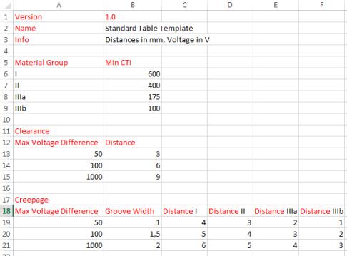
Version | Displays the format version of the standard table template. Do not change the version number. The standard table fails to load if you change the version number. |
Name | Displays the name of the standard table. You can edit the name of the table. |
Unit | Displays the units. The units are mm or inch. |
Material Group | Displays information about the material groups. You can define any number of material groups. Specify each group in a single line with the name of the group and a minimum CTI value. The CTI range of the material group is defined by its minimum value and the minimum value of the material group mentioned in the previous table. In the image, the material group I includes all CTI values greater than or equal to 600, the material group II all values from 400 to 599, and so on. You must specify the groups in the descending order of the CTI values. An empty line must exist between the last material group and the next parameter Clearance. |
Clearance | You can define any number of clearance rules. Each rule must be specified in a single line specifying the maximum voltage difference in column A and the clearance distance in column B. The voltage range of a rule is defined by the current value and the value of the previous rule. In the example, nets with a voltage difference between 1 and 50 must fulfill a clearance distance of 3 mm, nets with a voltage difference between 51 and 100 must fulfill a distance of 6 mm and so on. It is important that the rules are specified in ascending order and that there is an empty line between the last rule and the next parameter Creepage. |
Creepage | You can define any number of creepage rules. Specify each rule in a single line with the maximum voltage difference in column A, the grove width in mm or inch in column B, and a creepage distance for each material group in the subsequent columns. The voltage ranges of the creepage rules do not necessarily match with the voltage ranges of the clearance rules. However, the name of the material group in the respective column header must match the name as defined under Material Group and must have the word Distance as prefix. If you are using International Standards as a reference, you should not modify the columns. |
To Load a Standard Table
1. Click > . The Open dialog box opens.
2. Select the standard table .csv file and click Open.
The standard table does not work until the voltage is correctly defined in the Electric Nets tab. |
3. Click  to view the contents of the standard table file.
to view the contents of the standard table file.4. Click Close to close the Standard Table dialog box.
5. Click Select Source and select a source from the graphics window. Target nets are listed in the Source box. The distance values between the net pairs are automatically determined from the standard table and populated in the Clearance and Creepage Analysis dialog box.
You can manually edit the individual distance values in the corresponding Clearance Dist. and Creepage Dist. boxes. If a value is modified, the color of the box changes to blue.
Only the clearance distance and the groove widths are accurately displayed. The violation distance for the creepage depends on the insulation class on which the creepage path travels. This path is not known unless the path computation is performed. Therefore, the maximum violation distance is shown in the tables. This is the distance that corresponds with the worst insulation class found in the table. The exact creepage values are determined after the computation of each individual creepage path.
Import Parameters from a Spreadsheet
You can directly import the creepage, clearance, and groove width values between the net pairs from a Microsoft spreadsheet, as follows:
1. Rename the parts to include the underscore _ and the corresponding net name from the spreadsheet. This is essential to correctly assign the values of the net from the spreadsheet to the model component.
2. On the Electric Nets tab, click Import Nets From Spreadsheet.
The Open dialog box opens which contains a list of spreadsheets (.xlsx files).
3. Double-click to select the spreadsheet that you want to import.
4. Click Apply Electric Nets.
5. On the Analysis tab, click  and select the spreadsheet in the Open dialog box. The creepage, clearance, and groove width values are imported into the current configuration.
and select the spreadsheet in the Open dialog box. The creepage, clearance, and groove width values are imported into the current configuration.For each valid net pair, the corresponding values of the distances for creepage, clearance and groove width are automatically imported from the spreadsheet.
Violation Tolerance
The clearance and creepage analysis returns all paths with distance less than the specified violation distance. This is the case whether it is a custom parameter or the value that is automatically taken from a standard table.
If you want to view paths that are slightly above the violation distance, you can set a global threshold for violation tolerance in the Default violation tolerance box. The global threshold for violation tolerance is then added to each violation distance in the analysis and the following is displayed:
• All paths violating the distance value for each net pair.
• The paths with distance less the sum of the specified distance and the violation tolerance. These are reported as minor violations in the Results tab.