About the Geometric Tolerance Ribbon Tab
The Geometric Tolerance tab appears when you place a newly created geometric tolerance (GTOL) or select an existing geometric tolerance instance.
|
|
The Geometric Tolerance tab does not appear if you select more than a single GTOL instances.
|
You can use the following group commands on the Geometric Tolerance tab to modify properties of the selected geometric tolerance:
• References—Opens the References dialog box. It lists the details of references that were used to create the selected geometric tolerance. You can use the References dialog box to modify the references of the selected geometric tolerance.
|
|
The References commands are not accessible in Drawing mode.
|
• Symbol—Enables you to specify the geometric characteristic symbol for the selected GTOL. You can specify the geometric characteristics as straightness, flatness, circularity, cylindricity, profile of a line, profile of a surface, angularity, perpendicularity, parallelism, position, concentricity, symmetry, runout, or total runout.
• Tolerance & Datum—Enables you to specify the geometric characteristic symbol for the selected GTOL. You can specify the geometric characteristics as straightness, flatness, circularity, cylindricity, profile of a line, profile of a surface, angularity, perpendicularity, parallelism, position, concentricity, symmetry, runout, or total runout.
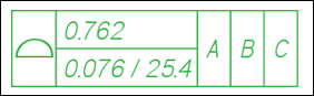
The Tolerance value text box allows you to specify a string that includes a numeric value of the tolerance preceded. Additionally, you can include symbols or modifiers from the Symbols gallery that will appear along with the tolerance value. This tolerance value string appears in the second compartment of the selected GTOL.
The Name text box displays the GTOL name generated by the system. You can modify the GTOL name. You can use the GTOL name within callouts to display the complete GTOL symbol and its value within other annotations.
The datum reference text boxes allow you to specify the primary, secondary, and tertiary datum reference. These references can be single or compound datum references along with their modifiers. Contents of these three datum references appear as three compartments of the selected GTOL.
The Composite Frame button enables the composite frame table that allows you to define the tolerance value, primary, secondary, and tertiary datum reference belonging to the composite GTOL frame. You can specify the tolerance value as well as content of datum reference compartments for every segment available within the composite GTOL symbol, in every row of the composite frame table. You can add, delete, shift up and down, or modify the row that represents the segments belonging to the composite GTOL frame.
Select the Share datum references option available on the Composite Frame table to share the same datum references between all the rows defined within the Composite Frame table. When you select this option, the primary, secondary, and tertiary references values of the first row are used for all the other rows, and you cannot modify these three datum references for other rows. The reference selection button is disabled for other rows. When the datum references are shared between rows of the Composite Frame table, the datum reference frame appears shared in the GTOL symbol that is displayed in the graphics area.
• Symbols—Enables you to access the symbols gallery. You can add symbols from the symbols gallery to the input text box of components that appear as compartments of the displayed geometric tolerance.
• Indicators—Enables the indicators table, where you can specify indicator types (Direction Feature, Collection Plane, Intersection Plane, and Orientation Plane), symbols, and datum reference that is displayed after the GTOL symbol according to requirements of ISO 1101-2012 standard.
The Indicators button is enabled when the tolerance is set to ISO standard. |
Each row of the Indicators table allows you to specify a single indicator that is displayed together with the GTOL symbol. You can add, delete, shift up and down, or modify the row representing individual indicators.
For the rows with Indicator types, you can specify the following symbols:
Indicator Types | Symbols |
|---|---|
Direction Feature | Angularity, Perpendicularity, Parallelism, or Runout |
Collection Plane | Angularity, Perpendicularity, Parallelism, or Symmetry. |
Intersection Plane | Angularity, Perpendicularity, Parallelism, or Symmetry. |
Orientation Plane | Angularity, Perpendicularity, Parallelism. |
The indicator types and symbols that are placed on the model are automagically added to the Parameters dialog box.
• Modifiers—Enables you to specify the modifier for the selected GTOL symbol. You can specify only one modifier for the selected GTOL symbol.
The following table lists modifiers that you can use with various geometric characteristics:
Modifier | Example | Geometric characteristics |
|---|---|---|
All Over — With the All Over toggle button, you can show the All Over symbol within the GTOL. Unselected by default for every newly created GTOL symbol. This option is enabled only with the Profile of a surface geometric characteristic. With other geometric characteristics, this option is disabled. This option is enabled when the All Around option is inactive. When the All Around toggle button is selected, the All Over toggle button is unselected and disabled. | 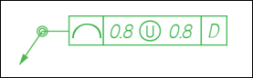 | Profile of a surface |
All Around — With the All Around toggle button, you can show the All Around symbol within the GTOL. Enabled only with the Profile of a line or Profile of a surface geometric characteristics. With other geometric characteristics, this option is disabled. This option is enabled when the All Over option is inactive. When the All Over toggle button is selected, the All Around toggle button is unselected and disabled. This toggle button is unselected by default for every newly created GTOL symbol. | 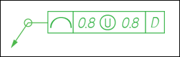 | Profile of a line Profile of a surface |
Unilateral — With the Unilateral toggle button, you can display the unilateral profile tolerance according to the alternate practice described in the ASME standard | 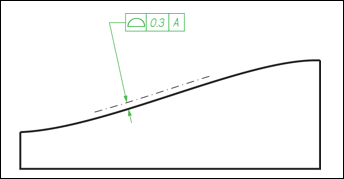 | Profile of a line Profile of a surface |
Flip This option is available only when you select the Unilateral modifier. |  | Flips the direction of the GTOL with Unilateral modifier. |
Boundary — With theBoundary toggle button, you can display the Boundary modifier used to control of the surface defined by a positional tolerance relative to a boundary. | 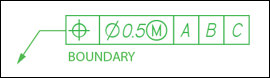 | Position |
• Additional Text—Enables you to specify additional text that is displayed above, below, on the left and on the right of the frame of the selected GTOL.  —Aligns lines of the text along the rows of a composite frame. Applicable to text on the right of the frame. When you click on the Additional Text panel, the additional text starts from the first row of the composite frame. The text is aligned with the remaining rows of the composite frame with spacing between the rows of text.
—Aligns lines of the text along the rows of a composite frame. Applicable to text on the right of the frame. When you click on the Additional Text panel, the additional text starts from the first row of the composite frame. The text is aligned with the remaining rows of the composite frame with spacing between the rows of text.• Leader—Enables you to control the arrow style of the leader displayed for the selected GTOL.
• Options—Enables you to control the position of the model-driven GTOL shown in the drawing.
Use the following options to control the position of the model-driven geometric tolerance:
◦ Options — This option is enabled only in Drawing mode. This option allows you to control the position of the model driven GTOL shown in drawing.
▪ Placement Position — You can set the placement position of the selected GTOL as Driven by model.
▪ Attachment — You can set the attachment point of the selected GTOL as References driven by model or Attach point(s) driven by model.
◦ Designation — This option is disabled in Drawing mode. This option allows you to designate annotation elements as control characteristics.
▪ Designate — Select Control Characteristics to designate the annotation elements of the selected GTOL as control characteristics.