Using the Synchronize Dialog Box
Use options in the Synchronize dialog box to minimize machining time by having all the work center heads carry out different machining operations simultaneously.
This topic explains various options in the dialog box and how the synchronization changes appear before and after synchronization.
Dialog Box Options
The dialog box has the following table columns:
• Head 1, Head 2, Head 3, and Head 4—Displays steps created on Head 1, Head 2, Head 3, and Head 4 of the work center.
• Time—Displays the machining time of each step in every column.
• Machining Time—Displays the total machining time for steps on every head in their respective columns.
• Delete— Delete a synchronization operation. Right-click the operation in the table and click Delete.
The top portion of the dialog box has the following options:
• View—Displays either a Synchronized view or a Machining Order view of NC toolpaths. With the synchronized view, you can select toolpaths for synchronization. With the machining order view you can see the order in which the toolpaths are executed on the machine.
• Gantt Chart—Displays details of a synchronized operation in a chart format.
• Display Toolpath—Enables you to highlight the selected toolpaths in the graphics window. By selecting the check box, you can accurately select points in the graphic window for synchronization.
The bottom portion of the dialog box has the following options:
• Start of Toolpath—Synchronizes the start of an NC step on one Head to another step on another Head, and so on.
• Point on Toolpath—Synchronizes a point on an NC step on one Head to another point on an NC step on another Head, and so on.
• Driving Head—The lead head on which the tool paths will be machined first.
•  —Starts playing the tool path. The synchronized tool paths start machining at the same time. You can see the tool paths machining simultaneously in the graphics window
—Starts playing the tool path. The synchronized tool paths start machining at the same time. You can see the tool paths machining simultaneously in the graphics window• Click  —Pauses a tool path.
—Pauses a tool path.• Click  —Stops playing the tool path.
—Stops playing the tool path.• Click 
—Plays the tool path from the current cutting tool location till the next synchronization in the operation.
• Slider—As the tool moves along the tool path you can adjust the slider to make the cutting tool move faster or slower.
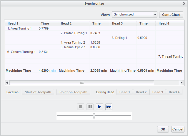
Example: Appearance Before the Start of Synchronization
Tool paths created using Head 1, Head 2, Head 3, and Head 4 are displayed as follows:
Example: Appearance After the Start of Synchronization
The synchronized tool paths are displayed as follows:
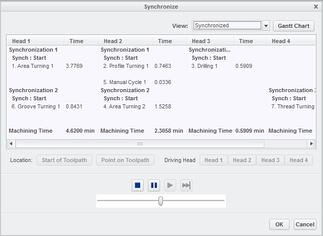
Here Synchronization 1 in the Head 1, Head 2 and Head 3 columns indicate that this machining process is the first synchronization operation. Synch : Start indicates the start of synchronization. This synchronization is for the following steps:
• Area Turning 1 on Head 1, Profile Turning 1 on Head 2, and Drilling 1 on Head 3
Similarly, Synchronization 2 in the Head 1, Head 2, and Head 4 columns indicate that this machining process is the second synchronization operation Synch : Start indicates the start of synchronization. This synchronization is for the following steps:
• Groove Turning 1 on Head 1, Area Turning 2 on Head 2, and Thread Turning 1 step on Head 4
The numbering of the synchronization operations follows the order in which the synchronization operations are created and not the order of the steps listed in the table. |