Using Parameters in Face Milling
You can specify multiple cuts to depth using the STEP_DEPTH and NUMBER_CUTS parameters. The system will compute the number of cuts according to STEP_DEPTH, compare with NUMBER_CUTS, and use the greater value. If you want just one cut at full depth, you can set NUMBER_CUTS to 1 and STEP_DEPTH to a relatively large value (greater than thickness of the stock to be removed).
The following illustration shows facing down the workpiece, with STEP_DEPTH = 10 (greater than part thickness) and NUMBER_CUTS = 2.

1. STEP_OVER
2. Approach motion
3. Overtravel motions
4. Exit motion
For Assembly machining, or workpiece with no geometry, these parameters will be interpreted differently: NUMBER_CUTS will determine the amount of slices, and STEP_DEPTH—the offset between slices, that is, the first slice will be offset from the selected face by(NUMBER_CUTS-1)*STEP_DEPTH. |
The number of cuts per slice is determined in a similar way using the combination of the STEP_OVER and NUMBER_PASSES parameters. However, if NUMBER_PASSES is set to 1, the STEP_OVER value will be ignored and only one pass per slice will be made. This is helpful and meaningful only when a large enough tool is used.
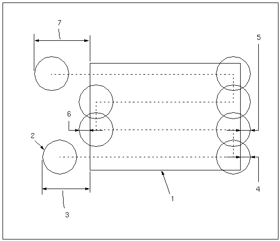
In the example in the following illustration, ENTRY_EDGE = LEADING_EDGE, CLEARANCE_EDGE = HEEL, and NUMBER_PASSES = 1. The tool makes one cutting pass. The approach motion of the tool (1) equals APPROACH_DISTANCE + START_OVERTRAVEL + tool radius. The exit motion (2) equals EXIT_DISTANCE + END_OVERTRAVEL + tool radius.
The BOTTOM_STOCK_ALLOW parameter specifies the stock allowance on the surface being faced. The default, dash (-), sets the bottom stock allowance to 0.
The tool path can be extended past the selected surface edges using the START_OVERTRAVEL and END_OVERTRAVEL parameters. The APPROACH_DISTANCE and EXIT_DISTANCE parameters apply to the first approach into a slice and the last exit from a slice, respectively. The APPROACH_FEED and EXIT_FEED can be specified for these motions if desired, otherwise, CUT_FEED will be used. All these parameters are measured with respect to a certain point of the tool, defined by the ENTRY_EDGE and CLEARANCE_EDGE parameter values.
When you set the parameter TRIM_TO_WORKPIECE to YES, the value CENTER is considered for CLEARANCE_EDGE and ENTRY_EDGE parameters. The other values are ignored. As a result, the center of the tool is used for measuring the approach and exit motions. |
The following graphic illustrates the approach, exit, and overtravel motions based on the parameter values if ENTRY_EDGE is HEEL and CLEARANCE_EDGE is LEADING_EDGE.
1. Reference part (selected face)
2. Tool
3. APPROACH_DISTANCE + START_OVERTRAVEL
4. END_OVERTRAVEL
5. START_OVERTRAVEL
6. END_OVERTRAVEL
7. EXIT_DISTANCE + END_OVERTRAVEL
The CLEARANCE_EDGE parameter specifies which point of the tool is to be used for measuring the exit motions and the overtravel motions when the tool leaves the material:
• HEEL (default)—The heel of the tool.
• CENTER—The center of the tool.
• LEADING_EDGE—The leading edge of the tool.
The ENTRY_EDGE parameter is similarly used to measure the motions where the tool approaches material. It has the same values as CLEARANCE_EDGE (LEADING_EDGE is the default).
The following illustration shows the overtravel motion depending on CLEARANCE_EDGE.
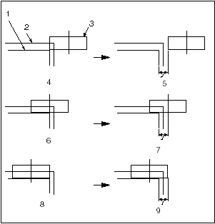
1. Reference part (selected face)
2. Workpiece
3. Tool
4. CLEARANCE_EDGE = HEEL
5. END_OVERTRAVEL
6. CLEARANCE_EDGE = CENTER
7. END_OVERTRAVEL
8. CLEARANCE_EDGE = LEADING_EDGE
9. END_OVERTRAVEL
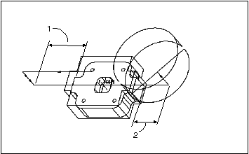
The entire part is used to calculate tool clearance. That is, when ENTRY_EDGE is LEADING_EDGE or CLEARANCE_EDGE is HEEL, the tool is tangent to the entire section of the part (as shown in the following illustration).

1. Tool
2. Part outline
3. Cut motion
This NC sequence is intended to be used for facing down the workpiece; therefore, no gouge avoidance checking for internal islands or adjacent walls, will be performed.