Creo NC Concepts
Design Model
The Creo design model, representing the finished product, is used as the basis for all manufacturing operations. Features, surfaces, and edges are selected on the design model as references for each tool path. Referencing the geometry of the design model sets up an associative link between the design model and the workpiece. Because of this link, when the design model is changed, all associated manufacturing operations are updated to reflect the change.
Parts, assemblies, and sheetmetal parts may be used as design models.
The following illustration shows an example of a design model—a valve housing.
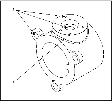
1. Holes to be drilled
2. Surfaces to be milled
Workpiece
The workpiece represents the raw stock that is going to be machined by the manufacturing operations. Its use is optional in Creo NC. The benefits of using a workpiece include:
• Automatic definition of extents of machining when creating NC sequences.
• Dynamic material removal simulation and gouge checking.
• In-process documentation by capturing removed material.
The workpiece can represent any form of raw stock; such as bar stock or casting. It may be created easily by copying the design model and modifying the dimensions or deleting/suppressing features to represent the real workpiece.
The following illustration shows an example of a workpiece—a casting.
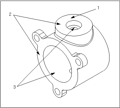
1. Holes removed — not part of casting
2. Dimensions increased to allow for material removal
3. Dimensions decreased to allow for material removal
If you have a ASSEMBLY license, the workpiece can also be created directly in Manufacturing mode by referencing geometry of the design model.
As a Creo part, the workpiece can be manipulated as any other: it can exist as an instance of a part family table; it can be modified and redefined.
Manufacturing Model
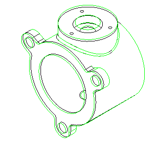
A regular manufacturing model consists of a design model (also called "reference model" since it is used as a reference for creating NC sequences) and a workpiece assembled together. As the manufacturing process is developed, the material removal simulation can be performed on the workpiece. Generally, at the end of the manufacturing process the workpiece geometry should be coincident with the geometry of the design model. However, material removal is an optional step. The following illustration shows a manufacturing model, with the reference part (shown in black) assembled inside the workpiece (shown in green).
If you are not concerned with material removal, you do not have to define the workpiece geometry. Therefore, the minimum configuration of a manufacturing assembly is one reference model.
Depending on your machining needs, the manufacturing model can be an assembly of any level of complexity, and can contain any number of independent reference models and workpieces. It can also contain other components that may be part of the manufacturing assembly, but have no direct effect on the actual material removal process (for example, the rotary table or clamps).
When a manufacturing model is created, it generally consists of the following separate files:
• The manufacturing model—manufacturename.asm
• The reference model—filename.prt
• The workpiece (optional)—filename.prt
In case of a more complex assembly configuration, additional part and assembly files may also be included in the manufacturing model. The manufacturing model configuration is reflected in the model tree.
Part and Assembly Machining
In previous releases of Creo NC, you could create two separate types of manufacturing models:
• Part machining—The manufacturing model contains one reference part and one workpiece (also a part).
• Assembly machining—No assumptions are made by the system as to the manufacturing model configuration. The manufacturing model can be an assembly of any level of complexity.
Currently, all Creo NC is based on Assembly machining. However, if you have legacy Part machining models, created in previous releases, you can retrieve them and work with them. Certain machining techniques are slightly different in Part machining. These differences are noted in appropriate sections of documentation.
The major difference between Part and Assembly machining is that in Part machining all the components of the manufacturing process (operations, workcells, or NC sequences) are part features that belong to the workpiece, while in Assembly machining these are assembly features that belong to the manufacturing assembly.