Using the Tools Setup Dialog Box
The Tools Setup dialog box allows you to define, modify, delete, and view details of tools used for NC machining.
The menu bar of the Tools Setup dialog box contains the following menus:
File—Contains the following commands:
• New—Define a new tool.
• Open Tool Library—Retrieve tool from the tool library.
◦ By Reference—Establishes a direct association with the library model. You cannot modify the parameters for the tool using the Tools Setup dialog box.
◦ By Copy—Copies the tool information into the manufacturing model. The tool parameters for the NC sequence can be modified using the Tools Setup dialog box.
◦ Use Outline—Reads in the model parameters and geometry, and generates the tool outline by projecting the external profile of all components of the selected tool model to the XZ-plane of the TIP coordinate system. This option is available only for the tool types TURNING and TURN-GROOVING.
• Open Parameter File—Retrieve a tool from the saved tool parameter file (files with the .xml, .tpm, tprm, or .txf extension)
• Open Std Size—Open a tool with standard size and dimensions.
• Save Tool—Save the selected tool along with the tool parameters. The tool parameters are saved in a file with the same name as that of the tool and have the .xml extension.
• Save As—Select and export a single tool or multiple tools to a tool exchange file. The tool exchange file is saved with the default name <workcell_name><head_x_optional> with the .txf extension. You can use this file to transfer tools. from one manufacturing model to another.
• Save Tool List—Save current tool table information for all tools to a file with the . xml extension. The default file name is <tool_dialog_tool_list>.
• Done—Finish the tool setup and close the Tools Setup dialog box.
• Quit—Abort the tool setup.
Edit—Contains the following commands:
• Delete—Delete the selected tool or select multiple tools and delete them simultaneously. You cannot delete a tool used in an NC sequence or by a step in the Process Manager.
• Replace—Replace the selected tool with a tool of the same type from the files system.
• Replace from Workcell—Replace the selected tool with a tool of the same type from the current or any other workcell.
|
|
The commands Save As, Replace, and Replace from Workcell are available if you start the Tool Manager from the Machine Tool Setup dialog box. They are not available if you start it while redefining an NC or CMM step.
|
• Table Comments—Opens the Setup Tool Table Comment dialog box.
• Sketch—Modify the tool using the sketcher.
View—Contains the following commands:
• Where Used—Opens the Information Window. The Information Window displays the list of NC sequences in which the listed tools are used.
• All Tools—Displays the tool.inf file in the Information Window. The tool.inf file contains the properties of all the listed tools.
• Auto Preview—Allows you to toggle the auto preview functionality. Click Auto Preview to see the section view of the tool in the preview window. To remove the auto preview functionality, clear the check box adjacent to Auto Preview by clicking it.
|
|
If you close the Tools Setup dialog box without closing the tool preview window, the next time you open the Tools Setup dialog box, Creo NC checks if the auto preview functionality is on. If the auto preview functionality is on, Creo NC opens the tool preview window.
|
The toolbars of the Tools Setup dialog box contain the following icons:
 —Define a new tool. When you click , Creo NC displays a pictorial representation of all tools that you can define for an NC sequence or workcell.
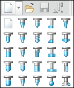
If you click  without selecting a tool type, Creo NC displays the tool setup options for the default tool for the workcell or the NC sequence.
without selecting a tool type, Creo NC displays the tool setup options for the default tool for the workcell or the NC sequence.If you access the Tools Setup dialog box while defining an NC sequence, Creo NC displays the pictorial representation of only those tools that are relevant for the NC sequence that you want to create. |
 —Retrieve tool from the tool library.
 —Save the selected tool along with the tool parameters.
 —Display the details of the selected tool in printable format in the Creo Parametric browser.
 —Delete the selected tool.
 —View the selected tool in a separate window. The modifications that you make to the tool setup are automatically updated in this preview window.
 —Start the Column Setup Builder to create custom views.
Show Details/Hide Details—A toggle button to display the tool parameter tabbed pages.