Exercise - Assigning Location Priority
In this exercise, you will learn how to use  Priority to route wires and the impact the priority has on changing the routing paths. In this exercise, you will route 3 wires W-01, W-02 and W-999 using Optimize routing and Put On Wire. Click here to download model for the exercise related to assigning location priority. Save the compressed folder LocationPriorityModels.zip to your computer and extract it. Open cabling_assembly.asm. Set OPTIMIZE_PUT_ON_WIRE as the working harness. Select OPTIMIZE_PUT_ON_WIRE from the Saved Orientations list.
Priority to route wires and the impact the priority has on changing the routing paths. In this exercise, you will route 3 wires W-01, W-02 and W-999 using Optimize routing and Put On Wire. Click here to download model for the exercise related to assigning location priority. Save the compressed folder LocationPriorityModels.zip to your computer and extract it. Open cabling_assembly.asm. Set OPTIMIZE_PUT_ON_WIRE as the working harness. Select OPTIMIZE_PUT_ON_WIRE from the Saved Orientations list.Workflow:
1. Import logical information from the Creo Schematics file.
2. Regenerate the assembly.
3. Designate the components as connectors.
4. Set priority for locations as Optimize or Put On Wire to find the shortest path.
Import Logical Information from the Creo Schematics File
1. Click  Import. The WIRELIST IMP menu appears.
Import. The WIRELIST IMP menu appears.2. Click Creo Schematics to import logical information of the wires, connectors, and components in your assembly. The REF XML menu appears. This information includes the reference designator, pin-to-pin connection information, and parameter values of connectors, pins, spools, wires, and cables.
3. Select Whole XML. The File Open dialog box opens.
4. Double-click optimize_put_on_wire.xml file.
5. Click Done/Return. This imports the logical information from the .xml file to the assembly.
6. Click Done in the WIRELIST IMP menu.
Regenerate the Assembly
1. Click  Update. The OBJECTS menu appears.
Update. The OBJECTS menu appears.2. Click Select All.
3. Click Done Sel.
4. On the status bar, click . The Regeneration Manager dialog box appears.
. The Regeneration Manager dialog box appears.5. Click Regenerate to regenerate the model with the new values that were imported from the .xml file.
The regeneration is now complete.
Designate the Components as Connectors
1. Click  Auto Designate. The Auto Designator dialog box opens.
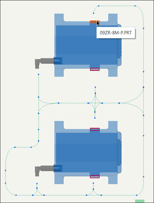
Auto Designate. The Auto Designator dialog box opens.2. From the Reference Des column, select LOGICAL-1 and select the component from the graphic window to designate it as a connector 09ZR-8M-P.
The following image shows the component selection of the connector from the graphic window:
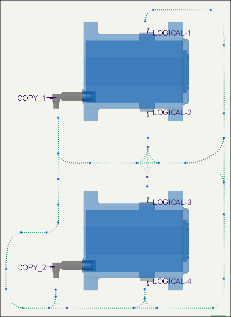
3. Follow step 2 and designate LOGICAL-2, LOGICAL-3 and LOGICAL-4 as connectors as shown in the following image:
4. Click Apply.
5. Click Close.
Set Priority for Locations as Optimize or Put On Wire to Find the Shortest Path
To Assign Optimize Priority to the Network
If you want to optimize the shortest path with at least one location for all cables in a network, set the routing priority as Optimize.
1. Click > . The REQD LOCS menu appears.
> . The REQD LOCS menu appears.2. Select Optimize.
3. Click Done.
4. Click  Route Cables. The Route Cables dialog box opens.
Route Cables. The Route Cables dialog box opens.5. Click  to retrieve cables from the logical reference. The Find Cables dialog box opens.
to retrieve cables from the logical reference. The Find Cables dialog box opens.6. Select the wires W-01, W-02 and W-999 and click  .
.
.7. Click OK. The Route Cables dialog box appears.
8. Click Apply.
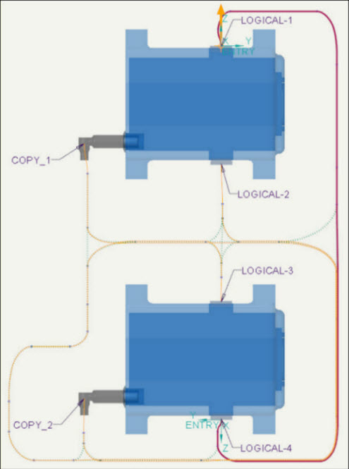
The following image shows wire W-01, routed between connectors LOGICAL-1 and LOGICAL-4 through a common location using Optimize.
To continue to the next exercise, select and delete the wires W-01, W-02 and W-999 from the Model Tree and click > . |
To Assign Put On Wire Priority to the Network
1. Click Route Cables. The Route Cables dialog box opens.
Route Cables. The Route Cables dialog box opens.2. Click to retrieve cables from the logical reference. The Find Cables dialog box opens.
to retrieve cables from the logical reference. The Find Cables dialog box opens.3. Select wire W-02 and click .
.4. Click OK. The Route Cables dialog box appears.
5. Click OK.
It is necessary to route wire W-02 to apply Put On Wire priority.
6. Click > . The REQD LOCS menu appears.
> . The REQD LOCS menu appears.7. Select Put On Wire.
8. Select W-02 wire from the graphic window.
9. Click Done.
10. Click Route Cables. The Route Cables dialog box opens.
Route Cables. The Route Cables dialog box opens.11. Click to retrieve cables from the logical reference. The Find Cables dialog box opens.
to retrieve cables from the logical reference. The Find Cables dialog box opens.12. Select wires W-01 and W-999 and click .
.13. Click OK. The Route Cables dialog box appears.
14. Click Apply.
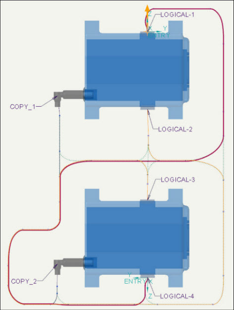
The wires W-01 and W-999 are now routed in the network through a common location with wire W-02. The following image shows the shortest path taken by wire W-01 between connectors LOGICAL-1 and LOGICAL-4 using Put On Wire.
The following table shows an overview of the change in routing paths for the wires W-01, W-02 and W-999 using Optimize priority and Put On Wire priority.
W-01 | W-02 | W-999 | |
|---|---|---|---|
Standard Routing | 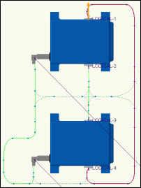 | 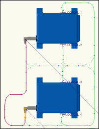 | 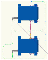 |
Optimize Routing | 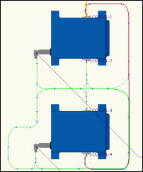 | 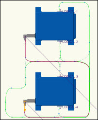 | 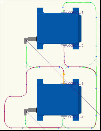 |
Put On Wire | 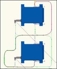 | 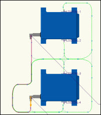 | 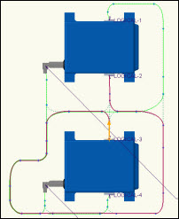 |