About Shields
To Manually Route a Shield Wire
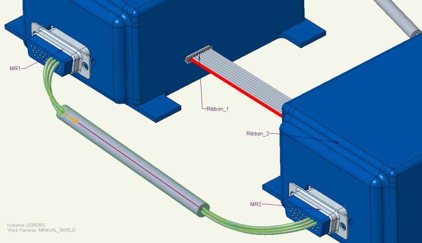
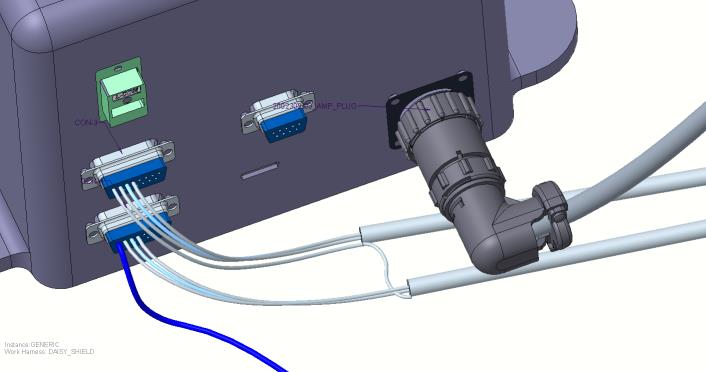
Use this procedure to manually route a shield wire. The shield wire is always attached to the cable sheath and is routed after you define the cable sheath locations.
Refer the cabling_assembly.asm sample assembly to learn how route a shield wire in the cabling model. Sample models are available at <Creo load point>\Common Files\help\sample_models\cabling. Open cabling_assembly.asm. Set MANUAL_SHIELD as the working harness. Select MANUAL_SHIELD from the  Saved Orientations list.
Saved Orientations list.1. Click  Route Cables. The Route Cables dialog box opens.
Route Cables. The Route Cables dialog box opens.2. Find the cable with the conductors and the shield to route.
In the sample assembly, select CABLE_1 from the Model Tree. Select CABLE_1:4 from the Route Cables dialog box, right-click, and click Route as Shield.
3. Select the cable in the list and define From and To locations for the cable sheath. The cable sheath is created in the graphics window.
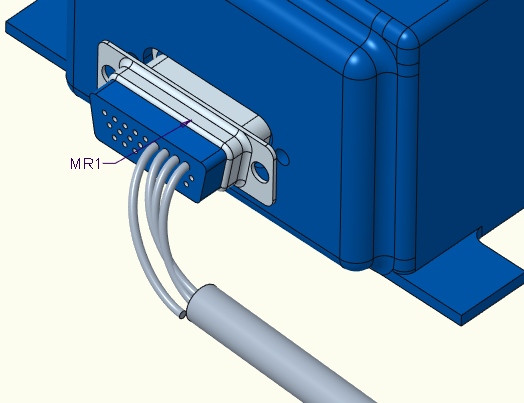
In the sample assembly, click From and select connector MR1 from the graphics window. The SEL ENTRYPRT menu appears. Select CS4 and click Done Sel.
4. Click OK.
The shield wire is automatically terminated at the cable sheath.
To Autoroute Shields
The shielding of a cable is defined in the wiring schematic.
You can autoroute shields if you define the shielding of a cable in the following ways:
• Connect one end of the conductor or shield to the cable and connect the other end of the shield to the connector and entry port.
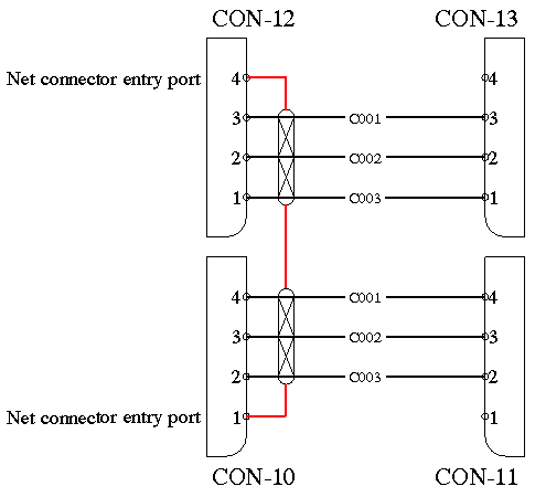
In the following figure, the red line indicates the shield conductor of the cable.
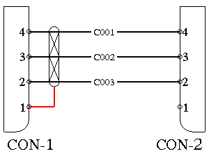
For this cable shield, the logical reference shows that one end of the conductor or shield is connected to the cable while the other end of the shield is connected to the connector and entry port.
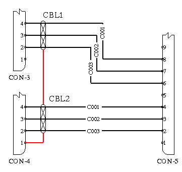
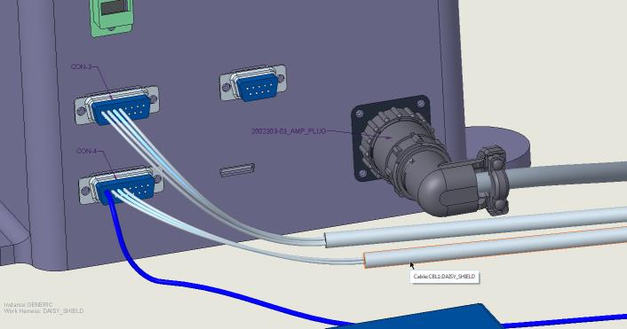
• Use cable shields that are daisy chained.
The following figure shows a daisy chained cable shield. The red line indicates the shield conductor of the cable.
In the sample assembly, set DAISY_SHIELD as the working harness. Select DAISY_SHIELD from the Saved Orientations list.
Saved Orientations list.1. Click . The Route Cables dialog box opens.
. The Route Cables dialog box opens.2. Click  to retrieve cables from the assembly or from a logical reference. The Find Cables dialog box opens.
to retrieve cables from the assembly or from a logical reference. The Find Cables dialog box opens.3. Select the cables with shields defined in the logical data and click OK. The cables appear in the list on the left and route automatically.
In the sample assembly, do the following:
a. Select cable CBL1. As the shield is connected to the cable at both the ends, Cabling automatically interprets the locations to be a cable location and net connection port 1 of CON-4.
b. To route the shield manually, from the Route Cables dialog box, select the shield wire, right-click, and clear the From box.
c. Click Options and click the Allow Location check box.
d. Select the cable sheath location on CBL2. The shield is routed.
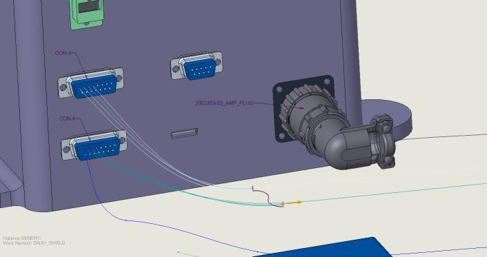
In the following figure, the shield net consists of multiple net entry ports. In this case, the conductor is considered incomplete and the center shield cannot be autorouted.
If the cable shield is daisy chained, the entry port connector must be of TYPE ROUND or FLAT to accept multiple connections. |