Defining a Single Projection Arrow for an Auxiliary View
You can define a single projection arrow style for an auxiliary view according to the JIS B 0001 and JIS Z 8316 standards. You can modify the length and position of the arrow and its associated text as follows:
• Select the text and move it to a desired location without moving the arrow.
• Drag the arrow from its either end to move it to a desired location along with the text.
• Change the arrow length by selecting its arrow head and dragging it to a desired length.
By default, the single projection arrow is placed at the midpoint of the selected entity between the auxiliary view and the original view located on the view boundary as shown in the following example:
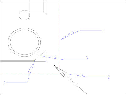
1. View boundary
2. Projection arrow
3. Mid point of the selected edge
4. Referenced edge
If you select a datum plane or a reference entity that does not have a midpoint, the system uses the midpoint of the view to determine the arrow placement position as shown in the following example:
1. View boundary
2. Projection arrow
3. Center of the view
When you define a single projection arrow for an auxiliary view created prior to Pro/ENGINEER Wildfire 4.0, the projection arrow is placed on the view boundary, with the center of the view and the original direction of the auxiliary view as references. |