About Displaying Tapered Threaded Shafts in a Drawing
You can display tapered threaded shafts in a drawing in the standard and cross-section views according to the JIS, ANSI, and ISO standards. To display such shafts, use the thread_standards Detail option in conjunction with the hlr_for_threads configuration option.
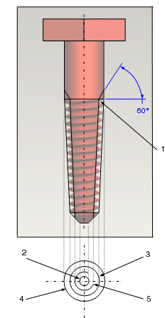
The following figure is a simplified representation of a tapered threaded shaft displayed as concentric circles overlaid on a detailed model:

1. Arc of one of the threads from the minor diameter at the base that is hidden in the top view
2. Outermost edge of the end chamfer
3. Outermost major diameter
4. Innermost major diameter
5. Outermost minor diameter of the thread at the outermost intersection surface