Example: Creating a DAST Connection
Consult the table below for a graphic representation of the types of steel connection you can create. Use it to determine which surfaces and check boxes to select and which values to enter during the connection definition process.
1. Click >  New Connector Element. The New Component dialog box opens.
New Connector Element. The New Component dialog box opens.2. If a connection has not been selected, click  to access the library and select a non-standard connection from either the STEEL CONSTRUCTION MM > DAST or the STEEL CONSTRUCTION INCH > DAST folder. The element appears in the preview area.
to access the library and select a non-standard connection from either the STEEL CONSTRUCTION MM > DAST or the STEEL CONSTRUCTION INCH > DAST folder. The element appears in the preview area.3. Click Next. The Element Definition dialog box opens. The reference collector for the first required surface is active.
4. Select the surface as indicated in the preview.
5. Repeat step 4 to select all required references.
6. If a selected surface is not planar, make sure that the Orient plane reference collector in the Optional References area is active and then select the orientation plane.
7. Click the Settings tab.
8. Select additional element sizes, such as angles, screws, or holes, from the tables.
9. Select or clear check boxes in the Options area.
10. Enter offset values and dimensions.
11. Click Preview to create the connection as a preview, click OK to create the connection using your definition, or click Cancel to cancel.
Type | Preview | Surfaces | Options | Values |
ANGLE CON. IW | 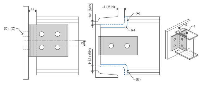 | I-Profile top Attach face | Top beam end cope Bottom beam end cope Attach holes thru all Attach holes thru next | |
ENDPLATE IH1, ENDPLATE IH2, ENDPLATE IH3 | 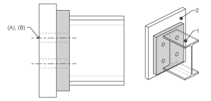 | I-Profile end Attach face | Attach holes thru all Attach holes thru next | |
ENDPLATE IS | 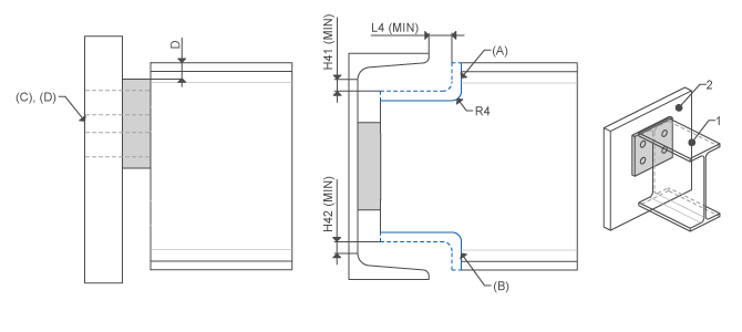 | I-Profile top Attach face | Top beam end cope Bottom beam end cope Attach holes thru all Attach holes thru next | D L4_MIN H41_MIN H42_MIN R4 |