About Automatic UDFs
Use the automatic UDFs functionality to define holes or cutouts to be made in parts that touch the XY-plane of the coordinate system for the part or the assembly. After you assemble a part or an assembly several times, use automatic UDFs to create all the defined holes or cutouts in the attaching parts in a single step.
The following example describes a typical automatic UDF workflow:
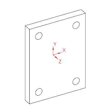
1. Consider a connector part with a hole pattern. The connector part uses the same hole pattern in a part that touches the end plate in the final design. Therefore, you can add an automatic UDF definition for the hole pattern on the coordinate system as shown in the following figure:
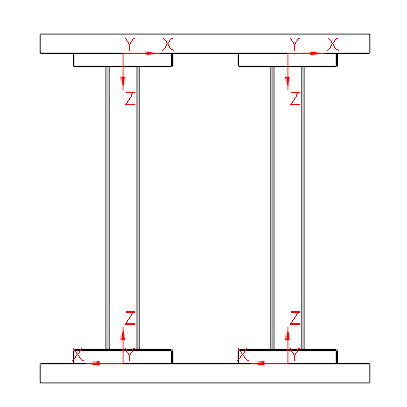
2. After you assemble the connector part several times (see the X, Y, and Z axes in the figure below), the holes in the two horizontal beams touching the connector part are missing. The XY planes of the CSYS in the connector parts touch the horizontal beams.
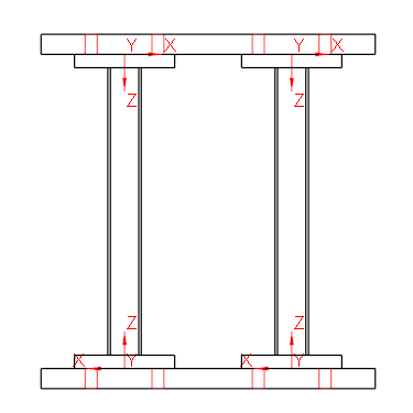
3. Use the automatic UDF functionality to create or update the UDFs you defined for the CSYS of the beams that touch the XY plane. The hole patterns are automatically created in the horizontal beams.
You can access and use the automatic UDF functionality in the following ways:
• From the Automatic UDFs dialog box.
• Use the automatic UDF functionality with nonstandard end plate connectors and the default setting for a hole pattern. In the Element Definition dialog box, select Auto UDF holes and enter hole depth values (UDF_T).
• Define point patterns using the Point Pattern command. You can include holes as well as automatic UDF definitions for the holes in the parts that touch the profile. Select the With automatic UDF attachment hole check box and enter a value for the attach hole depth the T box.
• Define a screw connection using the Creo Intelligent Fastener functionality. In the Screw Fastener Definition dialog box, select the Side 1 — Auto UDF check box or the Side 2 — Auto UDF check box and type a value for the offset.