使用管口進行多重分量混合:練習 1 - 萃取流體域
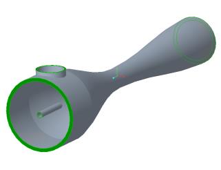
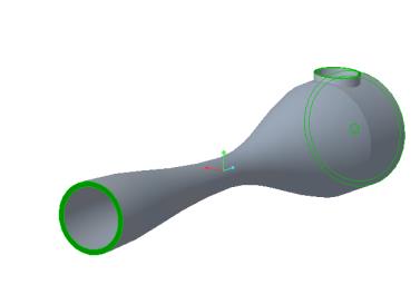
流體域萃取是在流體周圍建立封閉的幾何區域。
1. 按一下 > ,並導覽至 Advanced_FlowAnalysisModels 資料夾。按一下「確定」(OK)。
2. 按一下 > 。
3. 經由「檔案開啟」(File Open) 對話方塊瀏覽至 Multi-component-mixing 資料夾,然後選取 MIXING_NOZZLE.asm。按一下「開啟」(Open)。
4. 在「圖形」工具列中按一下  來顯示樣式元素。選取
  「著色」(Shading) 或
  「邊著色」(Shading with Edges)。
 來顯示樣式元素。選取
  「著色」(Shading) 或
  「邊著色」(Shading with Edges)。
5. 按一下「應用程式」(Applications) 標籤。
6. 按一下  Flow Analysis。Flow Analysis 標籤即會開啟。
 Flow Analysis。Flow Analysis 標籤即會開啟。
7. 按一下  「新專案」(New Project)。如果殘差繪圖開啟,請將其關閉。
 「新專案」(New Project)。如果殘差繪圖開啟,請將其關閉。
8. 按一下  「建立流體域」(Create Fluid Domain)。「建立流體域」(Fluid Domain Creation) 標籤即會開啟。
 「建立流體域」(Create Fluid Domain)。「建立流體域」(Fluid Domain Creation) 標籤即會開啟。
9. 按一下「開口」(Openings) 標籤。
10. 按一下「面」(Faces) 方塊。「曲面集合」(Surface Sets) 對話方塊就會開啟。
11. 在「曲面集合」(Surface Sets) 對話方塊中的「已包括曲面」(Included surfaces) 底下,以滑鼠右鍵按一下所有曲面,然後按一下「全部移除」(Remove All)。
12. 在圖形視窗中,按下 CTRL 鍵並選取如下所示的四個曲面。四個曲面即會顯示在「曲面集合」(Surface Sets) 對話方塊中的「已包括曲面」(Included surfaces) 底下。


13. 按一下「確定」(OK)。
14. 在「建立流體域」(Fluid Domain Creation) 標籤中,按一下  以建立流體域。
 以建立流體域。
分割邊界
1. 在模型樹中,以滑鼠右鍵按一下 MIXING_NOZZLE_1_FLUID.PRT。
2. 按一下  。系統會在新視窗中開啟該零件。使此視窗成為使用中視窗。
 。系統會在新視窗中開啟該零件。使此視窗成為使用中視窗。
3. 在 MIXING_NOZZLE_1_FLUID.PRT 視窗中,按一下「編輯」(Editing) 清單。
4. 按一下  「分割曲面」(Split Surface)。
 「分割曲面」(Split Surface)。
5. 在「分割曲面」(Split Surface) 標籤中,按一下「放置」(Placement)。
6. 選取管口開口,如下所示。

7. 按一下「所選輪廓」(Selected contours) 方塊,然後選取如下所示的燃料管開口。

8. 按一下  。
。
 。
。9. 在「操作」(Operations) 群組中,按一下  「再生」(Regenerate)。切換到視窗中的組件。
 「再生」(Regenerate)。切換到視窗中的組件。
新增模擬域
1. 在「模擬域」(Simulation Domains) 群組中,按一下  「選取模擬域」(Select Simulation Domains)。
 「選取模擬域」(Select Simulation Domains)。
2. 按一下「新增流體域」(Add fluid domain)。
3. 在模型樹中,選取 MIXING_NOZZLE_1_FLUID.PRT,然後按一下「確定」(OK)。
4. MIXING_NOZZLE_1_FLUID.PRT 出現在模型樹中。系統會自動建立邊界條件 BC_00001、BC_00002、BC_00003 和 MIXING_NOZZLE_1_FLUID 的邊界。它們會顯示在 Flow Analysis 樹中的 > 底下。
新增及重新命名邊界
1. 在「領域」(Domains) 底下選取 MIXING_NOZZLE_1_FLUID。
2. 在「操作」(Operations) 群組中,按一下  「新增邊界條件」(Add Boundary Condition)。「曲面集合」(Surface Sets) 對話方塊就會開啟。
 「新增邊界條件」(Add Boundary Condition)。「曲面集合」(Surface Sets) 對話方塊就會開啟。
3. 在圖形視窗中,選取如下所示的燃料管開口。

4. 在「曲面集合」(Surface Sets) 對話方塊中,按一下「確定」(OK)。BC_00004 會顯示在 Flow Analysis 樹的 「一般邊界」(General Boundaries) 下
5. 按一下「確定」(OK)。
6. 在 Flow Analysis 樹中的 > 底下,以滑鼠右鍵按一下 BC_00001 並選取  「重新命名」(Rename)。
 「重新命名」(Rename)。
7. 在「新名稱」(New name) 方塊中,鍵入 Nozzle_Outlet,然後按一下  。
。
 。
。8. 在 Flow Analysis 樹中的 > 底下,以滑鼠右鍵按一下 BC_00002 並選取  「重新命名」(Rename)。
 「重新命名」(Rename)。
9. 在「新名稱」(New name) 方塊中,鍵入 Nozzle_Side_Inlet,然後按一下  。
。
 。
。10. 在 Flow Analysis 樹中的 > 底下,以滑鼠右鍵按一下 BC_00003 並選取  「重新命名」(Rename)。
 「重新命名」(Rename)。
11. 在「新名稱」(New name) 方塊中,鍵入 Nozzle_Inlet,然後按一下  。
。
 。
。12. 在 Flow Analysis 樹中的 > 底下,以滑鼠右鍵按一下 BC_00004 並選取  「重新命名」(Rename)。
 「重新命名」(Rename)。
13. 在「新名稱」(New name) 方塊中,鍵入 Fuelpipe_Inlet,然後按一下  。
。
 。
。 「開啟」(Open)
 「邊界條件」(Boundary Conditions)