To Define General Preferences
The preferences you define remain active for the current session.
1. Click
Applications >
 Welding
. The
Welding tab opens.
2. Click
 Preferences
. The
Weld Preferences dialog box opens.
3. In the Weld preference for standard list, select the weld standard.
4. Select General on the list on left side of the dialog box.
5. Click the General tab, and set these preferences:
◦ To set the geometry that represents welds, under Weld geometry, select Light, Surface, or Solid.
|  Spot welds cannot use solid geometry, so when Solid is selected as the weld geometry type, spot welds are created using surface geometry. |
◦ To set the geometry that represents edge preparations, under Edge preparation geometry, select Solid or Light.
◦ To set the component that determines the contact surface in edge preparations, under Edge preparation driven by, select Part to use a selected part, or select Assembly to use all the selected parts in an edge preparation.
◦ To set the method of determining the lightweight weld trajectory, under Lightweight weld trajectory, select Automatic or User defined.
◦ To display the identification line in the weld symbol of ISO welds, select the Display identification line check box, and then select an option:
▪ To place the identification line in the weld symbol below the reference line, select Below reference line.
▪ To place the identification line in the weld symbol above the reference line, select Above reference line.
◦ Under Weld Sequence:
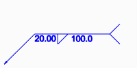
▪ To show the sequence ID number in the welding symbol tail, select the Display sequence ID check box. To hide the sequence ID number, clear the check box.
Show sequence ID | Hide sequence ID |
| |
▪ Select the Keep ID in sequence check box to keep the weld ID number the same regardless of subsequent actions (such as deleting previously defined weld features or reordering welds to different locations in the regeneration order).
6. Click the Family Table tab, select the Create family table instance check box, and set these preferences:
◦ To specify the suffix name for a new instance that will be created during edge preparation, and that will be added to a family table, type a name format in the New instance name format box. The part name plus the extension makes the instance name.
◦ Under Create edge preparation and weld features, select In generic model to create edge preparation and welding features in the generic model, or select In instance model only to create edge preparation and welding features in the single model instance.
7. Click the Properties tab, and set additional preferences as needed.
 Welding. The Welding tab opens.
 Welding. The Welding tab opens.
 Welding. The Welding tab opens.
 Preferences. The Weld Preferences dialog box opens.
