Exercise 6 – Assembling Dowel Pins by Mouse Click
1. In Creo Parametric set the working directory to <downloaded files location>\IFXTraining\IFX_Asm\Exercise6 and open ifx-exercise-6.asm.
2. Click
View >
 Saved Orientations
 and then click
ASSEMBLE.
3. Click
Tools >
Dowel Pin >
 Assemble by mouse click
. The
Select References dialog box opens.
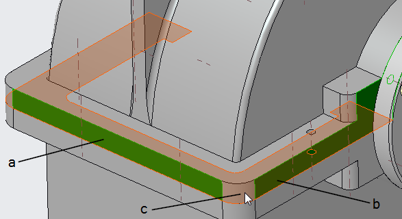
4. Select references as shown in the diagram and as described below:
a. In the first Position Reference box, select the surface for the first dimension reference.
b. In the second Position Reference box, select the surface for the second dimension reference.
c. Select a Placement Surface between the housing cover and housing parts.
d. Click OK. The Dowel Pin Fastener Definition dialog box opens.
5. In the diameter box select 8, in the length box select 22, and then click OK. After the definition is complete, the desired dowel pin snaps to the pointer and the Mouse Click Location prompt appears.
6. Click
View >
 Saved Orientations
 and then click
TOP.
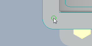
7. To assemble a dowel pin, enter the grid value 10 in the Mouse Click Location dialog box and click the position shown. The dowel pin is assembled and the holes are created.
|  The values in the Mouse Click Location dialog box show the dimensions relative to the selections made for positioning. If the position of the pointer is not valid, the numbers show a hyphen. The preview connection is shaded and the dowel pin cannot be placed. |
8. Middle-click to cancel the process.
9. Save and close the assembly.
10. Click File > Manage Session > Erase Not Displayed. The Erase Not Displayed dialog box opens.
11. Click OK to erase all files from memory.
 Saved Orientations and then click ASSEMBLE.
 Saved Orientations and then click ASSEMBLE.
 Saved Orientations and then click ASSEMBLE.
 Assemble by mouse click. The Select References dialog box opens.
 Saved Orientations and then click TOP.