Under Results > Responses, select  Topology Element Density. Then under Results > Isosurfaces, select an option:
Topology Element Density. Then under Results > Isosurfaces, select an option: Topology Element Density. Then under Results > Isosurfaces, select an option: Isosurface to show an isosurface that encloses all the regions where the density is greater than the lower cutoff value.
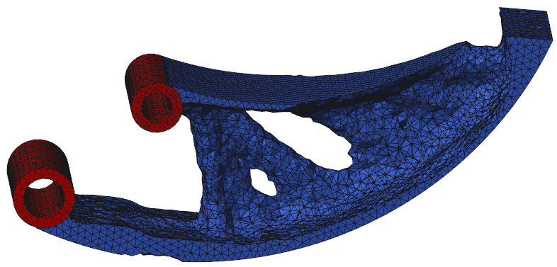
 Isosurface with Topology Region to show the same isosurface as above, along with the topology region as it appeared before material was removed to show the isosurface.
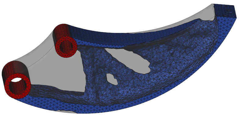
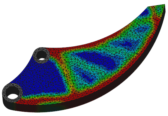
 Filled Elements to show each element filled completely with its result value color. The results are averaged to the elements.
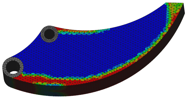
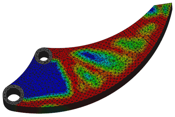
 Filled Contours to show contour lines based on grid result values. The results are averaged to the grids, so the contour lines appear smoother.
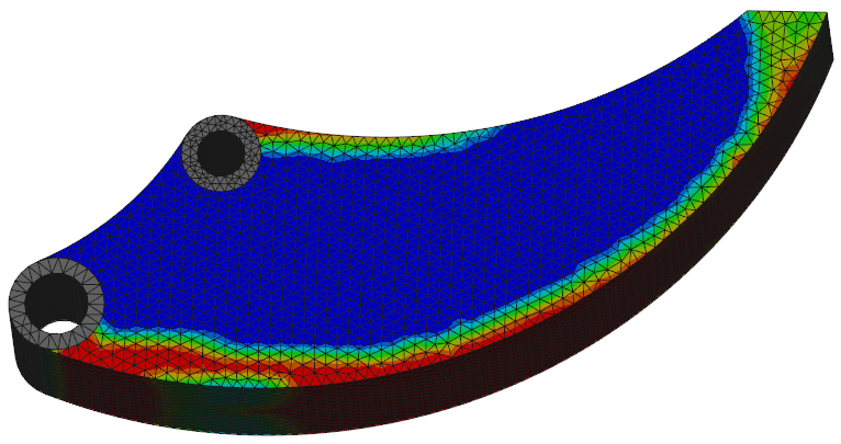
 No Section—Shows the model without a cross section. Use this option to remove the cross-sectional view.
 X Direction—Perpendicular to the x-axis.
 Y Direction—Perpendicular to the y-axis.
 Z Direction—Perpendicular to the z-axis. Z Direction, and slide the Section Upper Cutoff slider to show cross sections along the z-direction.
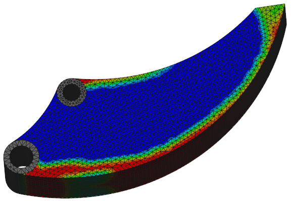
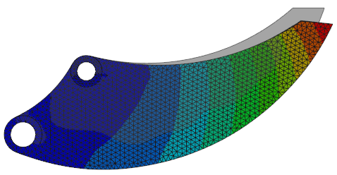
 Displacement.
 Undeformed—Without deformation.
 Static—A static deformed shape.
 Oscillate—A deformed shape that is animated by scaling the displacements with a sine wave. The animation moves smoothly.
 Ramp—A deformed shape that is animated by scaling the displacements with a sawtooth wave that ramps the displacement from zero to the scale factor. The animation pauses at each step.
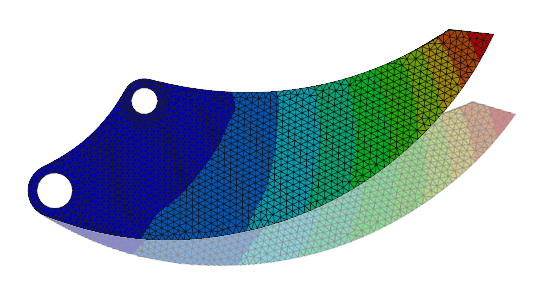
 Show Undeformed Shape. The undeformed results appear on top of the Static, Oscillate, or Ramp options.